Cambridge Audio 550A & 650A
affect the Tape Out connections. It is advisable to turn the Volume control fully anti-clockwise before
switching the amplifier on.
9. Balance
This control allows you to adjust the relative output levels of the left and right channels. In the central
position the output from each channel is equal. This control only modifies the sound through your
loudspeakers and the Pre-Out sockets – it does not affect the signals sent through the Tape Out
connections.
10. MP3 Input
This source input allows you to connect a portable audio device such as an MP3 player, plugged into
either the rear panel Phono/RCA input pair (labelled ‘MP3’) or the front panel 3.5mm stereo-jack input
(labelled ‘MP3 In’).
Press the MP3 button on the front panel to select the input, or insert a device into the front panel
socket which automatically selects the input and overrides the rear Phono/RCA sockets.
Note:
Whilst plugging a device into the front panel automatically selects the MP3 input, any other
input can still be selected once this has been done. As a result you may, if desired, leave a device
permanently plugged into the front panel.
11. CD, Tuner/DAB, DVD, Aux
Push the appropriate input selection button to select the source component that you wish to listen to.
The signal selected is also fed to the Tape Out sockets so that it may be recorded. The input should
not be changed whilst recording (but the recorded signal can be checked using the tape input Tape
Monitor).
12. Tape Monitor
This control lets you listen to the output signal from a tape recorder or signal processor connected to
the amplifier's Tape In/Rec Out sockets. When Tape Monitor is selected, the source component
chosen by the input selection buttons continues to be routed to the Rec Out sockets for recording or
processing.
Summary of Contents for AZUR 550A
Page 13: ...550A 650A Exploded Diagram ...
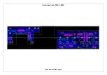
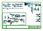
Page 17: ...Cambridge Audio 550A 650A Front Panel PCB Layout ...
Page 21: ...Cambridge Audio 550A 650A Speaker PCB Layout ...
Page 25: ...Cambridge Audio 550A 650A Input PCB Layout ...
Page 31: ...Cambridge Audio 550A 650A Preamp PCB Layout ...
Page 34: ...Cambridge Audio 550A 650A Volume PCB Layout ...
Page 44: ...Cambridge Audio 550A 650A AMP Layout ...
Page 49: ...Cambridge Audio 550A 650A Mains PCB Layout ...
Page 52: ...Cambridge Audio 550A 650A Protection PCB Layout ...
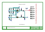
Page 61: ...IC Pin Layouts for the Cambridge Audio Azur 550A 650A Amplifier LM393D U6 ...

