background image

SAFETY PRECAUTIONS & IMPORTANT NOTES 


1.

Check that the rear of the product indicates the correct supply voltage 

for you area. 


2.

 The lighting flash with the arrowhead within an equilateral 

triangle is intended to alert the user or service agent to the 
presence of dangerous voltages within the product enclosure 
that may be of sufficient magnitude to constitute a risk of 
electric shock to persons. 


3.

 The exclamation point within an equilateral triangle is 

intended to alert the user or service agent to the presence of 
important operating and maintenance (Servicing) instructions 
in the literature accompanying the appliance. 
 

4.

 This product complies with EEC Low Voltage (73/23/EEC) and 

Electromagnetic Compatibility (89/336/EEC) Directives when used and 
serviced in accordance with this manual.  For continued compliance all 
components marked safety and EMC critical must only be replaced by 
Cambridge Audio approved parts. 
 

5. 

Any unauthorised design alterations or additions will void the 

manufacturer’s warranty; furthermore the manufacturer cannot accept 
responsibility for personal injury or property damage resulting therefrom. 
 
6. When servicing, care should be taken to observe the original routing 
and dressing of the leads and it should be confirmed that they have been 
returned to normal after re-assembly. 
 

Notes on chip component replacement 

Never reuse a component that has been removed from a PCB 
Notice that the minus side of a tantalum capacitor may be damaged by heat 


COPYRIGHT NOTICE. 


© 2005 Audio Partnership PLC. All rights reserved. 


Cambridge Audio and Azur are registered trademarks of Audio Partnership PLC.


This document 

may not be reproduced, distributed, transmitted, displayed, published, or broadcast without the 
express written prior permission of Audio Partnership PLC. 
Alteration or removal of any trademark, copyright, or other notice from this content is prohibited.


Information provided in this document is provided solely for the use of official service agents in 
repairing and servicing Audio Partnership PLC products.


3

Summary of Contents for Azur 640P

Page 1: ...mption 5W 5W 5W Gain 1kHz 39dB 39dB 55dB Input Impedance 47k 47k 100R Nominal Output 300mV 300mV 300mV Sensitivity for Nominal Output 3 35mV 3 35mV 0 5mV THD 20Hz 20kHz 0 009 0 005 0 002 RIAA Curve Ac...

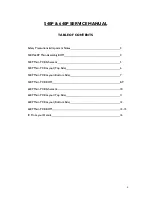
Page 2: ...40P Main Assembly BOM 4 540P Main PCB Schematic 5 540P Main PCB Layout Top Side 6 540P Main PCB Layout Bottom Side 7 540P Main PCB BOM 8 9 640P Main PCB Schematic 10 640P Main PCB Layout Top Side 11 6...

Page 3: ...5 Any unauthorised design alterations or additions will void the manufacturer s warranty furthermore the manufacturer cannot accept responsibility for personal injury or property damage resulting the...

Page 4: ...191 300 PY912 EU PSU Unit 1 GPG411200500WA00 PY913 CU PSU Unit 1 GPU351200500WA00 PY868 Australia NZ PSU Unit 1 GPS411200500WA01 PY867 UK PSU Unit 1 GPB411200500WA00 4021 411200 107 Cambridge Audio Az...

Page 5: ...00p NPO R22 47k C23 220p NPO MM R23 22R C24 100u 25V NP R24 22k G1 L L R C25 100n Ceramic C26 100n Ceramic MM phono input V PAD V PAD GND PAD D8 1N4004 R25 47R R26 3k9 G1 R27 1k2 R28 220R G1 R29 7k5 C...

Page 6: ...Cambridge Audio Azur 540P Phono Stage AP15219 4 Main PCB Layout Top Side AP15220 4 Superior Performance Moving Magnet Phono Module To enhance viewing please print to A3 6...

Page 7: ...Cambridge Audio Azur 540P Phono Stage AP15219 4 Main PCB Layout Bottom Side To enhance viewing please print to A3 7...

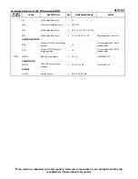
Page 8: ...CAPACITORS 100p NPO Ceramic 5mm Pitch 2 C18 C22 220p NPO Ceramic 5mm Pitch 2 C19 C23 4 7n NPO Ceramic 5mm Pitch 2 C39 C40 39n 5 Polyester Film 5mm Pitch 2 C14 C30 CMEA393J063RB050 Mini Box metallised...

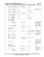
Page 9: ...18 volt 1A TO220 Positive Voltage regulator 1 U1 To be mounted on AP15814 1 heatsink shield 7918 18 volt 1A TO220 Negative voltage regulator 1 U2 To be mounted on AP15814 1 heatsink shield PY259 NE55...

Page 10: ...Vf 2V R100 3k 1 8W 2V Q23 BC560C R102 1k3 1 8W A K D12 Red Led Vf 2V R104 3k 1 8W 2V Q25 BC560C R67 1k2 18V R42 82R R43 150R sub direct C30 100n PE 63V C75 22p NPO 50V R15 130R 1 8W R16 130R 1 8W C88...

Page 11: ...io Azur 640P MM MC Phono Stage AP151199 1 Main PCB Layout Top Side AP15120 6 Ultimate Performance Universal Phono Module Power LED MM Input Output 12V 0 5A MC Input 18V 18V To enhance viewing please p...

Page 12: ...Cambridge Audio Azur 640P MM MC Phono Stage AP151199 1 Main PCB Layout Bottom Side To enhance viewing please print to A3 12...

Page 13: ...R43 470R 0 25W metal film 1 2 R58 66 1K2 0 25W metal film 1 2 R59 67 3K3 0 25W metal film 1 1 R1 1K87 0 25W metal film 0 10 4 R7 20 27 45 3 92K 0 25W metal film 0 10 2 R14 22 75K 0 25W metal film 0 1...

Page 14: ...nt on AP15814 1 heatsink with TO220 Silipad and Insulating Bush NE5532 Audio OpAmp 4155 320052 900 4 U3 4 5 6 2SA970GR PNP Very low noise 1301 970000 100 24 Q1 2 3 4 5 6 7 8 10 11 12 13 14 15 16 17 21...

Page 15: ...rite Bead on 24AWG 1503 000000 100 4 FB1 2 3 4 24AWG Tinned Copper Link Wire 5 LK1 2 3 4 5 10mm LINK PY584 ME2 5S Relay 4050 000005 002 1 RL 1 2 pole 2 way switch 2 SW1 2 SS004P022YPF8 MISCELLANEOUS N...

Page 16: ...40P 640P IC Pin Layout Details Main PCB 540P 640P 7818 U1 540P 640P 7918 U2 540P NE5532 U3 U4 640P NE5532 U3 U4 U5 U6 540P 2SA970GR Q1 2 3 4 640P 2SA970GR Q1 2 3 4 5 6 7 8 10 11 12 13 14 15 16 17 21 2...

Reviews: