background image


            White paper 


Fig 13 adds a THD vs. level plot for Class AB to the Fig 15 diagram, making it very clear that Class 

AB gives significantly greater THD above its transition point (say at -4 dB) than Class B, constant-

current Class XD  gives slightly less, and push-pull Class XD gives markedly less.  


Fig 14 returns to the THD/frequency format, and shows that XD push-pull gives lower THD over the 

range 1kHz - 30kHz than optimal Class B and is in fact better at all points.  

Summary of Contents for azur 840A

Page 1: ...d amplifier was one part of our new 8 Series A number of ideas came to the fore including the implementation of full microprocessor control for all functions nameable inputs and AV mode custom install...

Page 2: ...nd tweaks developed as part of the 840A s extensive measurement and listening test programme For a more in depth technical description of Class XD please refer to our UK Patent application number GB 0...

Page 3: ...both can be made to sound wonderful when well implemented What we were seeking with the development of Class XD was a way of incorporating a lot of the advantages and sound quality of Class A at a far...

Page 4: ...negative feedback factor in any linear amplifier falls with increasing frequency The 4 Ohm case shows lower overall gain due to the increased loading and a drop off of gain at each side due to falling...

Page 5: ...Class AB would seem to be a perfect compromise between Class A and Class B operation it does have some hidden issues It can be shown Ref 1 that if Class AB is used to trade off between efficiency and...

Page 6: ...is would abolish the AB gain changes that cause the extra distortion This was the purpose of our Class XD development program could it be done The Class XD crossover displacement principle We can see...

Page 7: ...sinks it into the negative rail For convenience we have called the current injection subsystem The Displacer Similarly the upper transistor is The Source while the lower is The Sink The displacement...

Page 8: ...icated implementations could even vary with the signal We now have before us the intriguing prospect of a power amplifier with three output devices which if nothing else is novel The operation of the...

Page 9: ...eft from 0V to 8V Realisation There are several ways in which a suitable displacement current can be drawn from the main amplifier output node Resistive crossover displacement The most straightforward...

Page 10: ...ost cases is unregulated and carrying substantial 100 Hz ripple A regulated supply to the resistor could be used but this would be very uneconomic and even less efficient due to the voltage drop in th...

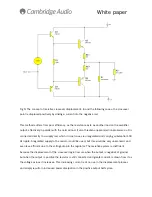
Page 11: ...use constant current displacement and this is where we started as in Fig 6 A constant current source is connected between the output and negative rail Efficiency is better as no output power is wasted...

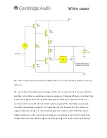
Page 12: ...was to move from a constant current to a voltage controlled current source VCIS whose output is modulated by the signal to further improve efficiency The most straightforward way to do this is to mak...

Page 13: ...h a real resistance giving 12 5 efficiency at full power moves to a constant current source with effective infinite impedance giving 25 and finally to a push pull controlled current source giving 50 I...

Page 14: ...nt varies in the correct sense for this This is equivalent to a decrease in output stage loading this is the exact inverse of what occurs with resistive displacement which increases output loading Lig...

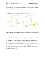
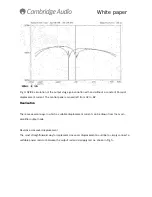
Page 15: ...adding relatively minimally to total amplifier cost Performance Measurements are presented here to demonstrate how the crossover displacement principle reduces distortion in reality Fig 9 THD vs freq...

Page 16: ...rent Classes of operation in fig 10 this shows distortion against amplitude at 10 kHz over the range 200mW 20W is plotted in this covers the power levels at which most listening is done 0 dB is 30W in...

Page 17: ...similar THD amplitude plot in Fig 11 now compares Class B with Class AB as most amplifier designers use and constant current XD Here the transition point from Class A to Class B is at 8 dB and gm doub...

Page 18: ...ed at 10 kHz power as before The transition points can also be seen to be not quite the same 8 dB for push pull versus 11 dB for constant current The salient point is that at 2 dB THD is very signific...

Page 19: ...antly greater THD above its transition point say at 4 dB than Class B constant current Class XD gives slightly less and push pull Class XD gives markedly less Fig 14 returns to the THD frequency forma...

Page 20: ...of complete output stage circuits The effects of transistor non linearity and so on are taken into account The results are therefore as real as extensive calculations can make them For comparison the...

Page 21: ...r distortion away from the central point where the amplifier output spends most of its time Below the transition point the amplifier actually runs in pure Class A with no crossover artifacts at all Ab...

Page 22: ...plifiers Electronics World Mar 1994 Class A efficiency canonical sequence 6 Self D Audio Power Amplifier Design Handbook as above p267 Class A distortion data 7 Moore B J An Introduction to The Psycho...

Page 23: ...Application Number 0505024 0 o This document is copyright Cambridge Audio Ltd o Reproduction in whole or in part can be authorized by prior written arrangement provided the source is acknowledged Clas...

Reviews: