background image

4  

Azur Class XD integrated amplifier

Checking  the  Power  Supply  Rating

For your own safety please read the following instructions carefully before attempting
to connect this unit to the mains.

Check that the rear of your unit indicates the correct supply voltage. If your mains
supply voltage is different, consult your dealer.

This unit is designed to operate only on the supply voltage and type that is
indicated on the rear panel of the unit. Connecting to other power sources may
damage the unit.

This equipment must be switched off when not in use and must not be used unless
correctly earthed. To reduce the risk of electric shock, do not remove the unit's
cover (or back). There are no user serviceable parts inside. Refer servicing to
qualified service personnel. If the power cord is fitted with a moulded mains plug
the unit must not be used if the plastic fuse carrier is not in place. Should you lose
the fuse carrier the correct part must be reordered from your Cambridge Audio
dealer.

The lightning flash with the arrowhead symbol within an equilateral
triangle is intended to alert the user to the presence of un-insulated
‘dangerous voltage’ within the product’s enclosure that may be of
sufficient magnitude to constitute a risk of electric shock to
persons.

The exclamation point within an equilateral triangle is intended to alert

the user to the presence of important operating and maintenance

instructions in the service literature relevant to this appliance.

This product complies with European Low

Voltage (73/23/EEC) and Electromagnetic Compatibility
(89/336/EEC) Directives when used and installed according to
this instruction manual. For continued compliance only
Cambridge Audio accessories should be used with this product
and servicing must be referred to qualified service personnel.

The crossed-out wheeled bin is the European Union symbol for
indicating separate collection for electrical and electronic
equipment. This product contains electrical and electronic
equipment which should be reused, recycled or recovered and
should not be disposed of with unsorted regular waste. Please
return the unit or contact the authorised dealer from whom you
purchased this product for more information.

Plug  Fitting  Instructions  (UK Only)

The cord supplied with this appliance is factory fitted with a 13 amp mains plug
fitted with a 3 amp fuse inside. If it is necessary to change the fuse, it is important
that a 3 amp one is used. If the plug needs to be changed because it is not suitable
for your socket, or becomes damaged, it should be cut off and an appropriate plug
fitted following the wiring instructions below. The plug must then be disposed of
safely, as insertion into a 13 amp socket is likely to cause an electrical hazard.
Should it be necessary to fit a 3-pin BS mains plug to the power cord the wires
should be fitted as shown in this diagram. The colours of the wires in the mains
lead of this appliance may not correspond with the coloured markings identifying
the terminals in your plug. Connect them as follows:

The wire which is coloured BLUE must be connected to the terminal which is
marked with the letter ‘N’ or coloured BLACK.

The wire which is coloured BROWN must be connected to the terminal which is
marked with the letter ‘L’ or coloured RED.

The wire which is coloured GREEN/YELLOW must be connected to the terminal
which is marked with the letter ‘E’ or coloured GREEN.

If your model does not have an earth wire, then disregard this instruction.

If a 13amp (BS 1363) plug is used, a 3amp fuse must be fitted, or if any other type
of plug is used a 3amp or 5amp fuse must be fitted, either in the plug or adaptor,
or on the distribution board. 

SAFETY PRECAUTIONS

Summary of Contents for azur 840A

Page 1: ...azur 840A Class XD Integrated Amplifier User s Manual ...

Page 2: ...ety instructions 5 Rear panel connections 6 Front panel controls 8 Remote control 10 Connections 11 Operating instructions 14 Amplifier setup 15 Multi Room 18 Custom installation use 19 CAP5 protection system 20 Troubleshooting 22 Technical specifications 23 Limited warranty 24 CONTENTS ...

Page 3: ...range giving very fine control an accurate logarithmic law and superbly accurate channel balance Input switching is also by high quality relays The 840A features separate transformer secondaries for left and right channels twin rectifiers and separate PSU s for dual mono operation of the left and right power amplifiers A separate transformer supplies the preamp making the 840A effectively a Pre an...

Page 4: ...nd servicing must be referred to qualified service personnel The crossed out wheeled bin is the European Union symbol for indicating separate collection for electrical and electronic equipment This product contains electrical and electronic equipment which should be reused recycled or recovered and should not be disposed of with unsorted regular waste Please return the unit or contact the authoris...

Page 5: ...it Do not situate it on a rug or other soft surface and do not obstruct any air inlets or outlet grilles Do not install near any heat sources such as radiators heat registers stoves or other apparatus including amplifiers that produce heat Do not stack multiple units on top of each other Do not place in an enclosed area such as a bookcase or in a cabinet without sufficient ventilation WARNING To r...

Page 6: ...om systems to be received by the amplifier Commands received here are not looped out of the Control Bus Refer to the Custom Installation section for more information Control Bus In Allows un modulated commands from multi rooms systems or other components to be received by the unit Out Loop out for control bus commands to another unit Also allows the 840A to control some Cambridge Audio units _ _ _...

Page 7: ...e subwoofers etc Tape In Out Connect to a tape deck or to the analog output sockets on a MiniDisc portable digital music player or CD recorder using an interconnect cable from the recorder s Line Out sockets to the amplifier s Tape In sockets The Tape Input circuit of the 840A is a monitor type different from the other 7 inputs For the 7 normal inputs the source selected for listening to will be s...

Page 8: ...speaker terminals on the back panel speaker sets A B or A and B This can be used for listening to an extra set of loudspeakers in another room Please note that care should be taken when choosing speakers if two loudspeakers are going to be used on each channel If the combined resistance measured on the loudspeaker terminals is too low the amplifier may not switch out of Standby mode until a suitab...

Page 9: ... refer to the Operating instructions and Amplifier setup section of this manual for more information Bass and Treble Press to release and rotate to allow subtle adjustments to the tonal balance of the sound Direct This control gives the audio signal a more direct path to the power amplifier stage of your amplifier bypassing the tone control circuits for the purest possible sound quality Volume Use...

Page 10: ...Standby mode Numerical buttons 1 8 8 Press to change the input source to the amplifier Button 8 toggles Tape Monitor on off Mode Press to switch between Volume and Balance modes REMOTE CONTROL Mute Mutes the audio on the amplifier The mute mode is indicated by MUTE appearing and the volume level being replaced by two flashing dashes in the display Press again to cancel mute Volume Increase or decr...

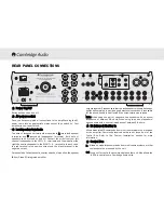
Page 11: ...n In Out Control Bus S P DIF Co axial Toslink Optical Digital Input 1 Right Left Right Left Balanced Audio Out Unbalanced Audio Out S P DIF Co axial Toslink Optical Digital Input 2 S P DIF Co axial Toslink Optical Right Left Right Left Manufactured in an ISO9002 approved facility On Off Power Class 1 Laser Product Luokan 1 Laserplaite Klass 1 Laserapparat Mains Voltage Selector Switch 115V 230V AC...

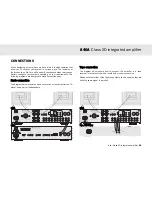
Page 12: ...tal Input 2 S P DIF Co axial Toslink Optical Right Left Right Left Manufactured in an ISO9002 approved facility On Off Power Class 1 Laser Product Luokan 1 Laserplaite Klass 1 Laserapparat Mains Voltage Selector Switch 115V 230V AC 50 60Hz N2409 Caution Risk of electric shock Do not open Avis Risque de choc electrique Ne pas ouvrir Achtung Vorm öffnen des gërates Netzstecker ziehen GND _ _ _ Right...

Page 13: ...er ziehen azur 840A Class XD Integrated Amplifier Power Rating 230V AC 50Hz Max Power Consumption 800W On Off N2409 Digital Outputs Power AC Designed in London England azur 840C Upsampling Compact Disc Player Max Power Consumption 40W www cambridge audio com RS232C IR Emitter In In Out Control Bus S P DIF Co axial Toslink Optical Digital Input 1 Right Left Right Left Balanced Audio Out Unbalanced ...

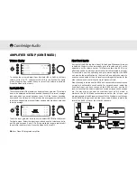
Page 14: ...rs are affecting the sound quality it may be necessary to adjust the tone controls to compensate The 840A has a custom made display on the front of the unit showing the current status and allowing you to access the 840A System Configure menus Here you can adjust the listening settings of the amplifier to personal preference The menu system is easy to navigate and control simply by using the input ...

Page 15: ...onfigure menu The menu options are Clip detector LCD brightness Speaker short detector Input gain trim Volume ramp Volume display and Fixed input gain To exit the System Configure menu and its sub menus press the Mode button again 840A Class XD integrated amplifier Azur Class XD integrated amplifier 15 Clip detector Speaker short detector Refer to the CAP5 section of this manual for more informati...

Page 16: ...s value and will not be adjustable by the volume control This feature allows the 840A to be effectively used as a stereo power amplifier for that selected input only For example as well as operating as a pure stereo amplifier the 840A can provide the amplification for the front left and right channels of a surround sound setup with an AV receiver providing amplification for the other channels and ...

Page 17: ...gital Input 1 Right Left Right Left Balanced Audio Out Unbalanced Audio Out S P DIF Co axial Toslink Optical Digital Input 2 S P DIF Co axial Toslink Optical Right Left Right Left Manufactured in an ISO9002 approved facility On Off Power Class 1 Laser Product Luokan 1 Laserplaite Klass 1 Laserapparat Mains Voltage Selector Switch 115V 230V AC 50 60Hz N2409 Caution Risk of electric shock Do not ope...

Page 18: ... Input 6 Input 5 Input 4 Input 3 Input 2 Input 1 Preamp Out Tape Out Tape In Input 7 Input 6 Input 5 Input 4 Input 3 Input 2 Input 1 Loudspeaker Terminals Impedance 4 8 ohms Input 1 Balanced Audio RS232C Control Bus Power PSU In International Patent Pending LeisureTech Electronics Pty Ltd Please ensure that loudspeaker terminals are fully tightened Veuillez s assurer que les bornes de l enceinte s...

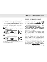
Page 19: ...m systems or remote IR receiver systems The Control Bus sockets are colour coded orange An IR Emitter Input is also provided that allows modulated IR remote control commands to be received electrically by the unit Commands on this input operate the unit only and are not looped out demodulated on the Control Bus Output An RS232 port is also featured which allows the 840A to be controlled by C I sys...

Page 20: ...m the loudspeakers and the display shows a flashing Cambridge Audio has developed a proprietary protection system to ensure reliability and a long life to its amplifiers This protection system comprises of five main protection methods 1 DC detection Indication Unit has switched off during operation display flashes DC ERROR Description CAP5 offers loudspeaker protection if the output of the amplifi...

Page 21: ...ntil the Standby ON switch is pressed to reset it Remedy The resistance on the loudspeaker terminals is too low Check to see if there is a short circuit between the loudspeaker terminals Note If the indication remains the same and multiple loudspeakers are being used on each loudspeaker output then please remove a pair and retry If too many loudspeakers are connected to any amplifier causing the l...

Page 22: ... they are switched on Make sure unit is not in mute mode There is no sound on one channel Ensure that balance control is in the correct position Check speaker connections Check interconnects TROUBLESHOOTING There is a loud buzz or hum Check turntable or tone arm for ground and connection lead fault Ensure no interconnects are loose or defective Ensure that your tape deck turntable is not too close...

Page 23: ...oduct as easy as possible Information in this document has been carefully checked for accuracy at the time of printing however Cambridge Audio s policy is one of continuous improvement therefore design and specifications are subject to change without prior notice If you notice any errors please feel free to email us at support cambridgeaudio com This document contains proprietary information prote...

Page 24: ... unaltered serial number and or you purchased from a Cambridge Audio authorised dealer This Warranty does not cover cosmetic damage or damage due to acts of God accident misuse abuse negligence commercial use or modification of or to any part of the product This Warranty does not cover damage due to improper operation maintenance or installation or attempted repair by anyone other than Cambridge A...

Page 25: ...840A Class XD integrated amplifier Azur Class XD integrated amplifier 25 ...

Page 26: ...azur 840A Part No AP18646 2 www cambridge a audio com ...

Reviews: