background image

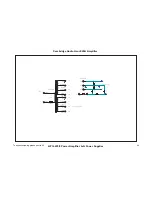
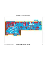
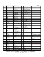
Cambridge Audio Azur 840A Amplifier IC Pin Layout

Details

TC9163AF

– Input PCB (U1)

NE5532

Input PCB - (U2, U3, U4, U5, U6, U7, U8, U9,
U14 & U18)
A-BUS PCB – (U1 & U3)
Pre-Amp PCB – (U1, U2, U9 & U12)

ULN2003A

Input PCB - (U16)
Pre-Amp PCB – (U4, U5 & U7)

BC337

Input PCB -  (Q1)
Pre-Amp PCB – (Q2, Q3, Q4 & Q5)
Front Panel PCB – (Q2, Q3, Q4 & Q5)
Right Hand Power Amp PCB – (Q11, Q31, Q32,
Q33, Q34, Q35 & Q36)
A-BUS PCB – (Q2, Q3, Q4, Q5 & Q6)
Left Hand Power Amp – (Q11)

TSOP18

Pre-Amp PCB - (U10)

PIC16F877A-I/SP

Front Panel PCB

48

Summary of Contents for azur 840A

Page 1: ...S into 4 Ohms THD unweighted 0 0015 1 kHz at 80 of rated power 0 015 20Hz 20kHz at 80 of rated power Frequency Response 10Hz 50kHz 1dB S N ratio ref 1W 8 Ohm 83dB Input Impedances Input 1 balanced 10 kOhm Inputs 2 7 68 kOhm Tape Input 68 kOhm Power Amp damping factor 110 at 1kHz Max power consumption 800W Minimum power consumption Active no signal 70W Standby 7W Bass Treble controls Shelving type ...

Page 2: ... Bottom Side 17 Input PCB BOM 18 Preamp PCB Schematic Relay Logic 19 Preamp PCB Schematic Tone Control 20 Preamp PCB Schematic Post Amp 21 Preamp PCB Board Layout Top Side 22 Preamp PCB Board Layout Bottom Side 23 Preamp PCB BOM 24 25 Power Amplifier Schematic Right Power Supplies PSU 26 Power Amplifier Schematic Right Channel 27 Power Amp Right PSU PCB Board Layout Top Side 28 Power Amp Right PSU...

Page 3: ...41 Hub PCB BOM 42 43 Rectifier PCB Schematic 44 Rectifier PCB Board Layout Top Side 45 Rectifier PCB Board Layout Bottom Side 46 Rectifier PCB BOM 47 IC Pin Layout Details 48 49 Technical Description 51 60 Procedure to upgrade the Control Pic Software 61 62 Notes 63 3 ...

Page 4: ...s 5 Any unauthorised design alterations or additions will void the manufacturer s warranty furthermore the manufacturer cannot accept responsibility for personal injury or property damage resulting therefrom 6 When servicing care should be taken to observe the original routing and dressing of the leads and it should be confirmed that they have been returned to normal after re assembly Notes on chi...

Page 5: ...Cambridge Audio Azur 840A Amplifier 840A Block Diagram To enhance viewing please print to A3 5 ...

Page 6: ...7 10 6 2 3 9 17 4 18 15 8 13 5 11 16 6 1 15 14 12 5 Cambridge Audio Azur 840A Amplifier 840A Exploded Diagram To enhance viewing please print to A3 6 ...

Page 7: ...840A Silver Front Panel Assy 8 PY1131 6574 150012E000 01 Azur 840 A B Front Panel Artwork AP186371 186381 Metalwork Only 8 PY1132 Azur 840 A Silver Front Panel Artwork AP186371 186381 Metalwork Only PY1133 6074 150005E000 Azur 840A Volume Knob Plastic Insert AP1743 6574 150015E000 Azur 840A Volume Knob Skin Black Azur 840A Volume Knob Skin Silver PY1135 3110 840000E000 LCD Display Highly Transflec...

Page 8: ...1 NOBLE16ENCODER POSITION FOR EXTRA SWITCH A K D2 BLUE LED ON STBY LED IR IN FROM JACK PHONO ON HUB PCB 15V IR GND IR IN RS232 GND R10 10R C9 100N CERAMIC SERIAL RX 232 C4 10U 16V C3 10U 16V R5 100R C20 100nF LOGIC GND C21 100n LOGIC GND LOGIC GND Q4 BC337 15V RS232 TX R13 22K R12 2K2 LOGIC GND SERIAL TX 232 Q3 BC337 5V D3 1N4002 RS232 RX R11 10K R9 22K LOGIC GND SERIAL RX 232 RS232 RX RS232 TX SE...

Page 9: ... Q1 5 Q2 6 Q3 7 Q4 14 Q5 13 Q6 12 Q7 11 QS 9 QS 10 U5 74HC4094 VDD 5V VSS LOGIC GND FROM SHEET 1 SERIAL CLOCK SERIAL DATA SERIAL STROBE SHIFT REG ENABLE 1 2 3 4 5 6 7 8 CN4 FFC 08WAY 1 2 3 4 5 6 7 8 CN5 FFC 08WAY 1 2 3 4 5 6 7 8 CN6 FFC 08WAY D 2 CLK 3 STB 1 OE 15 Q0 4 Q1 5 Q2 6 Q3 7 Q4 14 Q5 13 Q6 12 Q7 11 QS 9 QS 10 U6 74HC4094 VDD 5V VSS LOGIC GND 1 2 3 4 5 6 7 8 CN7 FFC 08WAY C8 100nF 5V C12 1...

Page 10: ...OT1 SW1 SW2 SW3 SW4 SW5 SW6 SW7 SW8 X1 SW9 SW10 SW11 C1 C2 C3 C4 C5 C6 C10 C11 C12 C13 C14 C15 C17 R1 R2 R3 R4 R6 D2 D3 R9 R10 R11 R12 R13 R14 R15 C7 C8 C9 C16 C18 C19 Q1 Q2 Q3 Q4 R5 C20 AP16370 3 C21 C22 R7 U2 U3 U4 U5 U6 C24 Q5 R17 R18 R19 Q6 C23 P2 P3 R16 CN2 R23 R24 Q8 R8 D4 D5 D6 D7 D8 To enhance viewing please print to A3 10 ...

Page 11: ...Cambridge Audio Azur 840A Amplifier AP16369 3 Front Panel PCB Layout Bottom Side To enhance viewing please print to A3 11 ...

Page 12: ...U2 U6 TRANSISTORS PY219 BC327 25 PNP Small Signal TO92 2 Q1 Q8 PY214 BC337 25 NPN Small Signal TO92 4 Q2 Q3 Q4 Q5 DIODES BLUE LED Blue LED 3mm UNI flat top 1 D2 1N4148 General purpose diode 4 D4 D5 D6 D7 e s a C 5 3 O D W m 0 0 4 8 D 1 W m 0 0 4 7 V 2 e d o i d r e n e Z 7 V 2 C 9 7 X Z B 1N4002 General Purpose Rectifier 1 D3 MISCELLANEOUS PY1141 D100 SSV 12 12 WAY FFC reverse needle type single r...

Page 13: ...GHT INPUT ONE RIGHT INPUT 1 L INPUT 1 L INPUT 1 R INPUT 1 R GND INPUT 1 L INPUT 1 L INPUT 1 R INPUT 1 R R22 100R R34 100R 3 2 1 8 4 U2 A NE5532 R35 100K R36 1K R37 1K 3 2 1 8 4 U4 A NE5532 R38 100K C13 47pF C14 47pF C15 47pF C22 47pF C23 47pF C24 47pF C25 47pF C26 47pF C27 47pF C28 47pF C29 47pF C30 47pF C31 47pF PREAMP OUT PREAMP OUT C32 47pF 15V 15V 15V 15V 3 2 1 8 4 U3 A NE5532 R42 100k R43 47K...

Page 14: ... OUT4 13 OUT3 14 OUT2 15 OUT1 16 U16 ULN2003A 9V 9V LOGIC GND INPUT 1 INPUT 2 INPUT 3 INPUT 4 INPUT 5 INPUT 6 INPUT 7 1 2 RL8 A RELAY TAPE MONITOR Q1 BC337 D1 1N4001 R11 10K INPUT PCB PREAMP PCB TO PREAMP LEFT TO PREAMP RIGHT 15V 15V 5V 9V LOGIC GND PREAMP OUT L PREAMP OUT R C65 100nF 100V LOGIC GND 5V LOGIC GND 1 2 3 4 5 6 7 8 CN8 FFC 08WAY FROM FRONT PANEL PCB 1 2 3 4 5 6 CN9 JST 2 5MM B6B XH A ...

Page 15: ...P LEFT 5 6 7 U2 B NE5532 5 6 7 U4 B NE5532 C18 22p C19 22p R48 1k R49 1k R50 1k R51 1k R52 100K R53 100K R54 100K INPUT AMPLIFIER 6 dB INPUT L INPUT R C9 1000uF 10V EL C10 1000uF 10V EL R39 100K R83 47R R84 47R C21 10U 16V NP C20 10U 16V NP 15V 15V 15V 15V D2 1N4001 To enhance viewing please print to A3 15 ...

Page 16: ...6 R8 R26 R27 R22 C13 C14 R37 R36 R9 U2 R38 R35 R39 C15 C22 C23 C24 C25 C26 C27 C28 C29 C30 C31 C32 C33 C34 R42 C38 R44 R45 C39 R43 U3 R41 C36 C41 U5 R46 R40 R47 C43 C44 L C51 C 5 2 C45 C 4 6 C47 C53 C60 C62 U7 U8 U6 U18 C54 C55 C56 C64 R67 R68 R66 R69 R70 R71 R72 R76 R78 R55 R56 R65 R73 R74 R77 R79 C65 AP16362 3 TO HUB PCB HUB SWITCHER RELAY DRIVER LOGIC C11 C12 C20 C21 C35 C37 C40 C42 C48 C49 C50...

Page 17: ...Cambridge Audio Azur 840A Amplifier AP16361 3 Input Board PCB Board Layout Bottom Side To enhance viewing please print to A3 17 ...

Page 18: ...rised Electrolytic Radial 5 2mm Pitch 2 5mm 20 C11 C12 C20 C21 C35 C37 C40 C42 C48 C50 C57 C59 C61 C63 C66 C68 C71 C77 10uF 35V Non Polarised Electrolytic Radial 5 2mm Pitch 2 5mm 14 C36 C38 C39 C41 C45 C47 C51 C53 C60 C62 C69 C70 1000uF 10V Electrolytic Radial 10mm Pitch 5mm 2 C9 C10 SEMICONDUCTORS e g a k c a P 8 2 P O S 1 U 1 y a r r A h c t i w S e u g o l a n A F A 3 6 1 9 C T 6 7 4 Y P PY116...

Page 19: ...VOLUME E L B A C E L B A C R19 100K LOGIC GND ON STBY LED CONTROL ON STBY LED R20 430R LOGIC GND R21 430R PHONES R PHONES L IN1 1 IN2 2 IN3 3 IN4 4 IN5 5 IN6 6 IN7 7 GND 8 COM 9 OUT7 10 OUT6 11 OUT5 12 OUT4 13 OUT3 14 OUT2 15 OUT1 16 U7 ULN2003A 9V 1 2 RL15 A RELAY 1 2 RL16 A RELAY 1 2 RL17 A RELAY BAL L BAL R BAL1 HI PHONE JACK OUT 1 2 RL18 A RELAY BAL 2 MAINS ON OFF RELAY INRUSH RELAY 5V 3 OPT 1...

Page 20: ...3 4 5 RL17 B RELAY 3 4 5 RL18 B RELAY 3 4 5 RL19 B RELAY 6 7 8 RL18 C RELAY 6 7 8 RL17 C RELAY 6 7 8 RL16 C RELAY R90 150R R91 2K2 R92 390R R93 2K2 R94 1K R95 2K2 2 5 dB 3 75 dB 5 5 dB BALANCE CONTROL 15V 15V R85 390R R96 390R R97 150R R98 150R 3 4 5 RL15 B RELAY 6 7 8 RL15 C RELAY 5 6 7 U9 B NE5532 TO VOLUME RIGHT 3 2 1 8 4 U9 A NE5532 3 4 5 RL16 B RELAY R99 47K R101 47K R102 47K R103 47K BALANCE...

Page 21: ...AL 1 2 3 4 5 6 7 8 9 10 11 12 CN5 FFC 12WAY XD ON OFF XD ON OFF LO ON 15V 15V POST AMPLIFIER CLIP OVERLOAD DC OFFSET OVERTEMP AUDIO TO L POWER AMP AUDIO TO R POWER AMP LOGIC GND 5V 9V PREAMP PCB PSU PCB CONN 15V 15V C23 100nF ceramic C26 100nF ceramic C7 10u 25V C30 10u 25V OPAMP DECOUPLING R106 470R PREAMP OUT L R107 47K R108 470R PREAMP OUT R R109 47K 1 2 CN10 JST 2 5MM B2B XH A 1 2 CN12 JST 2 5...

Page 22: ...71 R72 R73 R74 U5 U4 U7 U10 U9 U12 C18 R99 C21 R103 R77 R75 R76 R78 R79 R80 R81 R82 C16 C17 C24 C25 R102 C15 C22 C23 C26 U1 U2 R1 R2 R3 R4 R5 R6 R7 R8 R9 R10 R15 R16 R17 R18 R13 R14 R11 R12 C3 C6 C8 SW1 C2 C5 C1 C4 C9 C10 C20 C19 R 2 2 R85 R 8 6 R87 R 8 8 R 8 9 R90 R91 R92 R 9 3 R94 R 9 5 R 9 6 R 9 7 R98 C11 C12 C13 C14 C27 C28 C29 CN1 CN5 R84 D2 D3 Q1 R20 R21 R19 R100 R 1 0 5 R104 R55 R101 C7 C30...

Page 23: ...Cambridge Audio Azur 840A Amplifier AP16365 3 Pre amp PCB Layout Bottom Side To enhance viewing please print to A3 23 ...

Page 24: ...4 1 2 R 0 2 R 2 m l i F l a t e M W 5 2 0 R 0 3 4 8 0 1 R 6 0 1 R 2 m l i F l a t e M W 5 2 0 R 0 7 4 0 1 1 R 1 m l i F l a t e M W 5 2 0 K 0 1 0 0 1 R 3 8 R 2 m l i F l a t e M W 5 2 0 K 2 2 9 0 1 R 7 0 1 R 4 8 R 3 m l i F l a t e M W 5 2 0 K 7 4 9 1 R 1 m l i F l a t e M W 5 2 0 K 0 0 1 CAPACITORS 6 C 3 C 2 m m 3 h c t i P 0 1 V 0 5 c i m a r e C F p 0 1 4 3 C 1 m m 3 h c t i P 0 1 V 0 5 c i m a...

Page 25: ...ay vertical header 1 CN3 PY1141 D100 SSV 12 Flat film connector 12 way reverse needle type Single row contacts 2 CN2 CN5 PY1140 D100 SSV 08 Flat film connector 8 way reverse needle type Single row contacts 4 CN6 CN8 CN9 CN11 PY1157 D100 SSV 16 Flat film connector 16 way reverse needle type Single row contacts 1 CN4 9 1 L R 1 L R 9 1 y a l e R C D V 9 C D V 9 9 2 E M A 0 4 3 n i d e s u s A 1 W S 1...

Page 26: ...1 500mA RELAY SUPPLY J7 TERMINAL F4 20MM T1AL D19 1N4002 D20 1N4002 D21 1N4002 D22 1N4002 MAIN TRANSFORMER STANDBY TRANSFORMER J8 TERMINAL J9 TERMINAL C25 15000uF 63V C26 15000uF 63V 48V R 48V R J10 TERMINAL J11 TERMINAL J12 TERMINAL ORANGE BLACK RED J13 TERMINAL D23 1N4002 C27 1000uF 50V F7 T1A AL LVD 51V R POWER AMP SUPPLY RIGHT 3 6 4 5 RL3 B ME14FW009HS 3 6 4 5 RL4 B ME14FW009HS 1 2 RL3 A ME14F...

Page 27: ... A LM393 R70 1K8 5V IN R71 1M Q31 BC337 D14 1N4002 R72 4K7 LOGIC GND Q32 BC337 R73 10K CLIP DC OFFSET 5V IN PHONES OUT RIGHT LOGIC GND PREAMP PCB POWER AMP PCB CONN HI NORMAL R74 4K7 R75 10K R76 10K OUTPUT RELAY CONTROL HI NORMAL RIGHT 3 4 5 RL2 B RELAY Q36 BC337 R39 10K 1 2 RL2 A RELAY Q33 BC337 D7 1N4002 R82 4K7 Q34 BC337 R83 10K OUTPUT RELAY B OUTPUT RELAY A R50 10K R85 10K spare Q35 BC337 R16 ...

Page 28: ...Cambridge Audio Azur 840A Amplifier AP16373 3 Power Amp Right PSU PCB Layout Top Side To enhance viewing please print to A3 28 ...

Page 29: ...Cambridge Audio Azur 840A Amplifier AP16373 3 Power Amp Right PSU PCB Layout Bottom Side To enhance viewing please print to A3 29 ...

Page 30: ... Metal Film 8 R39 R50 R51 R64 R73 R83 R84 R89 16K 0 25 W Metal Film 3 R49 R54 R55 22K 0 25 W Metal Film 5 R15 R57 R67 R81 R100 47K 0 25 W Metal Film 8 R35 R38 R44 R45 R47 R65 R66 R86 56K 0 25 W Metal Film 1 R92 75K 0 25 W Metal Film 1 R91 100K 0 25 W Metal Film 4 R37 R97 R98 S 8 8 R 1 m l i F l a t e M W 1 R 3 3 pace off PCB S 1 4 R 1 n o b r a C W 1 R 0 7 4 pace off PCB 0R1 3 W Wire Wound 6 R19 R...

Page 31: ... 2SA1295 PNP Power Audio 3 Q13 Q14 Q17 MT200 0 0 2 T M 6 1 Q 5 1 Q 2 o i d u A r e w o P N P N 4 6 2 3 C S 2 7 4 1 1 Y P DIODES 1N4148 Small Signal Diode 18 D1 D6 D8 D10 D13 D17 D18 D30 D34 DIODE IN4148 1N4002 General Purp a k c a P 1 4 O D 3 2 D 4 1 D 7 D 3 r e i f i t c e R e s o ge 1N5404 General Purp a k c a P 7 2 O D 7 2 D 6 2 D 2 r e i f i t c e R e s o ge Clamp diodes e s a C 5 3 O D W m 0 ...

Page 32: ...g a k c a P 0 2 2 O T 2 U 1 r o t a l u g e R r a e n i L A 1 t l o V 5 5 0 8 7 e g a k c a P 0 2 2 O T 3 U 1 r o t a l u g e R r a e n i L A 1 t l o V 5 1 5 1 8 7 e g a k c a P 0 2 2 O T 4 U 1 r o t a l u g e R r a e n i L A 1 t l o V 5 1 5 1 9 7 DIODES 1N4002 General Purpose Rectifier 9 D15 D22 D24 DO41 Package e g a k c a P 1 4 O D 5 2 D 9 D 2 r e i f i t c e R e s o p r u P l a r e n e G 1 0 0...

Page 33: ...1 B LM393 R70 1K8 5V R71 1M 3 2 1 8 4 U1 A LM393 100deg C cutout CLIP DC OFFSET PREAMP PCB LEFT POWER AMP PCB CONN HI NORMAL R75 4K7 POSITIVE THERMISTOR LEFT MAINS FAIL IN J5 TERMINAL J6 TERMINAL 1 3 2 VR1 1K D7 1N5404 D9 1N5404 C18 100n ceramic R72 75K R73 56K R74 2K7 D14 12V D16 12V R76 2K7 1 3 2 VR2 10K R78 100K R79 100K D17 1N4148 D18 1N4148 R80 1K R81 22K C20 10U NP 16V 48V 48V DC OFFSET NULL...

Page 34: ...36 V 36 V 0V 115 DEG C Primary Secondary 230 V 0 V GREEN 4 38 V 5 5A 5 5A 100 mA RED ORANGE YELLOW 1 2 3 36 V 36 V 0V Secondary GREEN 4 38 V 5 5A 5 5A 100 mA J4 TERMINAL D15 1N4002 C11 1000uF 50V F1 T1A AL LVD 51V MAIN TRANSFORMER TO POWER AMP SUPPLY RIGHT C12 15000U 63V C13 15000U 63V C17 220uF 100V R38 33R 1W GREEN 48V IN 48V IN 48V IN 0V IN FROM RECTIFIER BOARD To enhance viewing please print t...

Page 35: ...3 D12 D13 Q10 Q11 Q9 D1 Q20 Q25 R6 R7 R8 R9 R15 R13 Q5 Q6 Q7 Q8 C6 Q19 C9 C10 R23 R24 R34 R32 R49 R51 R53 R55 C7 C1 C8 Q3 R2 R4 R5 D2 R14 R27 R52 R54 R33 R56 R57 R67 R1 R17 R10 R11 R12 R3 Q4 D10 Q1 Q12 C2 C4 R29 R18 R19 L1 R20 C17 R28 R58 C11 D7 D9 D15 R50 R75 R16 AP16694 4 RED BLACK ORANGE OUTPUT GND V 0V V D11 GREEN 38V AC BIAS VR1 R72 R74 D14 R73 R76 D16 C18 CN3 D17 D18 VR2 R78 R79 R80 R81 C20 ...

Page 36: ...Cambridge Audio Azur 840A Amplifier AP16693 5 Power Amp PCB Board Layout Bottom Side To enhance viewing please print to A3 36 ...

Page 37: ... 4 R16 R51 R64 R66 16K 0 25 W Metal Film 3 R49 R54 R55 22K 0 25 W Metal Film 4 R15 R57 R67 R81 47K 0 25 W Metal Film 5 R35 R47 R65 R73 R82 56K 0 25 W Metal Film 1 R73 75K 0 25 W Metal Film 1 R72 100K 0 25 W Metal Film 2 R78 R79 B C P f f o e c a p S 8 3 R 1 m l i F l a t e M W 1 R 3 3 B C P f f o e c a p S 1 4 R 1 m m 8 1 h c t i P n o b r a C W 1 R 0 7 4 0R1 3 W Wire Wound 6 R19 R22 R25 R26 Space...

Page 38: ...N 5 2 7 3 3 C B 4 1 2 Y P PY1149 2SA1295 PNP Power Audio 3 Q13 Q14 Q17 MT200 PY1147 2SC3264 NPN Power Audio 2 Q15 Q16 MT200 DIODES 1N4148 Small Signal Diode 18 D1 D6 D8 D10 D13 D17 D20 D23 D25 7 2 O D 9 D 7 D 2 r e i f i t c e R e s o p u P l a r e n e G 4 0 4 5 N 1 1N4002 General Pupose Rectifier 3 D15 D21 D22 DO41 ZENER 12V 400mW Zener BZX79 C12 2 D14 D16 400mW DO35 Case C g e d 0 0 1 p m e t g ...

Page 39: ...G 2 3 CN7 XLR FEMALE GND 1 G 2 3 CN8 XLR FEMALE IR OUT IR IN IR IN IR IN CN9 JACK CKX 3 5 12 3 5mm JACK 5V 3 OPT 1 GND 2 U6 TSOP1836 IR RECEIVER 5V LOGIC GND R44 220R 1 2 3 U7 A 4011 VDD 5V R45 220R 1 2 6 5 4 NC 3 U8 OP4N25 5 6 4 U7 B 4011 VDD 5V VSS LOGIC GND 8 9 10 U7 C 4011 VDD 5V 12 13 11 U7 D 4011 VDD 5V R46 220K R47 10K R48 10K 5V LOGIC GND R49 2R2 R50 100R Q4 BC337 R51 10K LOGIC GND C11 100...

Page 40: ...Cambridge Audio Azur 840A Amplifier AP16377 3 Hub PCB Layout Top Panel AP16378 3 AP16378 3 TX RX GND CHAS RS232 To enhance viewing please print to A3 40 ...

Page 41: ...Cambridge Audio Azur 840A Amplifier AP16377 3 Hub PCB Layout Bottom Panel To enhance viewing please print to A3 41 ...

Page 42: ...V Electrolytic Radial 5 2mm Pitch 2 5mm 2 C19 C37 220uF 35V Electrolytic Radial 8 4mm Pitch 3 5mm 1 C9 SEMICONDUCTORS 8 0 L I D 3 U 1 U 2 p m A p O l a u d e s i o n w o L 2 3 5 5 E N 9 5 2 Y P CD4011BE Texas Instruments Quad NAND gate IC N C B 1 1 0 4 D C i m e s l a n o i t a N s i e v i t a n r e t l A 7 U 1 0 2 2 O T 2 U 1 0 2 2 O T r o t a l u g e r A 1 V 2 1 2 1 8 7 6 0 L I D 8 U 1 r o t a l...

Page 43: ...ype single row contacts 13 way 1 CN15 m r o f e l b a c n n o c 2 3 2 S R r o F 6 1 N C 1 H X e p y t r e d a e h l a c i t r e v T S J 4 L I S H P 5 2 N N O C t u p n i d e c n a l a b r o F 5 N C 1 H X e p y t r e d a e h l a c i t r e v T S J 6 L I S H P 5 2 N N O C AP17339 3 IR Receiver Housing 2 Fit over D2 U4 and D1 U6 3 F 2 F 1 F 3 U 0 1 1 P 0 3 D L R A 1 1 E S U F Y L O P POLYFUSE 1 1A 30V...

Page 44: ...F J4 TERMINAL J5 TERMINAL 48V OUT 48V OUT J6 TERMINAL GREEN RED ORANGE YELLOW BROWN BLUE 1 2 3 1 2 36 V 36 V 0V 115 DEG C Primary Secondary 230 V 0 V GREEN 4 38 V 5 5A 5 5A 100 mA RED ORANGE YELLOW 1 2 3 36 V 36 V 0V Secondary GREEN 4 38 V 5 5A 5 5A 100 mA MAIN TRANSFORMER TO POWER AMP SUPPLY RIGHT VIOLET BLUE 3 1 4 2 BR1 BRIDGE BR 254 To enhance viewing please print to A3 44 ...

Page 45: ...Cambridge Audio Azur 840A Amplifier AP17575 2 Rectifier Board PCB Board Layout Top Side PARTNERSHIP 2005 AUDIO To enhance viewing please print to A3 45 ...

Page 46: ...Cambridge Audio Azur 840A Amplifier AP17575 2 Rectifier Board PCB Board Layout Bottom Side To enhance viewing please print to A3 46 ...

Page 47: ...is not soldered to PCB until PCB is fixed to amplifier heatsink MISCELLANEOUS T6A3 AL 6 3 Amp 20mm anti surge Fuse low breaking capacity 2 F1 F2 2 F 1 F 2 m m 0 2 r e d l o h e s u F 1 0 0 0 0 1 0 5 0 1 3 0 4 Cambridge Audio Azur 840A Amplifier Rectifier PCB BOM Note resistors capacitors and other generic electronic components are not usually stocked by the manufacturer Please obtain these locally...

Page 48: ...U14 U18 A BUS PCB U1 U3 Pre Amp PCB U1 U2 U9 U12 ULN2003A Input PCB U16 Pre Amp PCB U4 U5 U7 BC337 Input PCB Q1 Pre Amp PCB Q2 Q3 Q4 Q5 Front Panel PCB Q2 Q3 Q4 Q5 Right Hand Power Amp PCB Q11 Q31 Q32 Q33 Q34 Q35 Q36 A BUS PCB Q2 Q3 Q4 Q5 Q6 Left Hand Power Amp Q11 TSOP18 Pre Amp PCB U10 PIC16F877A I SP Front Panel PCB 48 ...

Page 49: ... PCB Q1 Q12 Q18 Left Hand Power Amp PCB Q1 Q12 Q18 Q30 MJE350 Right Hand Power Amp PCB Q2 Left Hand Power Amp PCB Q2 MPSA93 Right Hand Power Amp PCB Q3 Q4 Q5 Q6 Q20 Q22 Q24 Q27 Q28 Q29 Left Hand Power Amp PCB Q3 Q4 Q5 Q6 Q20 Q22 Q24 Q27 Q28 Q29 Q31 MPSA43 Right Hand Power Amp PCB Q7 Q8 Q9 Q10 Q19 Q21 Q23 Q25 Q26 Left Hand Power Amp PCB Q7 Q8 Q9 Q10 Q19 Q21 Q23 Q25 Q26 49 ...

Page 50: ... Left Hand Power Amp PCB Q13 Q14 Q17 2SC3264 Right Hand Power Amp PCB Q15 Q16 Left Hand Power Amp PCB Q15 Q16 CD4011BE A BUS PCB U7 7812 A BUS PCB U2 OP4N25 A BUS PCB U8 PIC16F627 04 P A BUS PCB U5 TSOP34837 A BUS PCB U4 TSOP34836 A BUS PCB U6 50 ...

Page 51: ...B AP16373 3_B Azur 840A front panel PCB AP16369 3 Azur840A input board PCB AP16361 3 Azur 840A preamp PCB AP16365 3 Azur 840A power amp Left PCB AP16693 4 Azur 840A power amp Right PCB AP16373 3_A Azur 840A A BUS Hub PCB AP16377 3 Azur 840A Rectifier PCB AP17575 2 Operating instructions summary Service Menu NOTES Logic signals are in upper case thus MAINS FAIL References to the PIC or the main PIC...

Page 52: ...s carries The main PIC The volume rotary encoder and control switches The LCD display Shift registers for driving the relays The RS232 interface for control and software updates U1 is the main housekeeping microcontroller for the amplifier it is a 16F977A PIC running at 20 MHz It handles all the control functions of the amplifier except for those on the A BUS hub PCB which are dealt with by anothe...

Page 53: ...utton in when the mains power is turned on The word DOWNLOAD appears on the LCD A PC running a Windows program is used to download the program The Hub PIC can in turn be reprogrammed by the main PIC This is done by the PGM MCLR HUB PROGRAM_DATA and PROGRAM_CLOCK lines that go to the Hub PCB via CN3 The Input PCB The input PCB carries Input buffers Input select relays Tape out buffer Input amplifie...

Page 54: ...he stereo image is shifted to the left The balance control attenuation steps are Step Nominal dB 0 0 1 1 3 2 2 5 3 3 4 4 4 5 5 5 5 6 6 8 7 7 7 8 8 8 The volume control is a relay driven stepped attenuator that gives 1 dB steps from 0 dB to 64 dB There are 2 dB steps from 64 dB to 76 dB and two final steps of 84 dB and infinity The final step also opens the power amplifier output relays to ensure t...

Page 55: ... channel is described in detail and the right channel description deals only with the differences Power Amplifier Left PCB This description is subdivided as follows Input stage DC trim system The Voltage Amplifier Stage Biasing system Output stage The XD Crossover Displacement system Power supplies Overload protection Clip detection DC offset protection Over temperature protection Speaker short ci...

Page 56: ...three rails The voltages given here are nominal as they depend on the exact value of the mains supply voltage The 48V rail supplies all the positive power to the amplifier The 48V rail powers only the amplifier output stage including the XD Crossover Displacement system The 51V rail provides negative power for the small signal circuitry This permits greater output as without it the negative going ...

Page 57: ... set up by R69 R70 and the comparator output goes low to 0V R71 provides a small amount of hysteresis to give clean switching The comparator has an open collector output and R75 is the external pull up resistor The output signal is passed to the main PIC Speaker short circuit detection When the amplifier goes from standby to ON the speaker outputs are checked for short circuits before the output r...

Page 58: ... GND to prevent ground loops and this use of the differential amplifier performs a change of reference so a clean signal reaches the hub amplifier seven if the two grounds have noise voltage between them The hub microcontroller U5 is a PIC16F72 This performs the following tasks Control Hub input switcher from IR commands Send input select data to main PIC Control Hub input switcher to prevent thum...

Page 59: ...s the grounds and prevents ground loops The optocoupler output drives Q4 through R47 Q4 collector if Q6 is off provides the IR signal to U7 A as mentioned above and also drives Q5 via R53 to re invert the signal and preserve its phase It is then OR ed with the PIC TX signal by U7 B and buffered by U7 C and U7 D to provide enough drive for the IR output R50 protects the output and C11 R49 isolate t...

Page 60: ...e button next to FIXED INP Select the input required Set the fixed gain using the volume control the OFF setting does not disable the input it leaves the input gain subject to the volume control Press Mode button to return to volume display To access the service menu Hold in the Mode button when mains power is switched on These are the menu options Speaker short detection on off DC offset detect o...

Page 61: ...4 seconds the following should be displayed on the LCD 2 Connect a Null Modem RS232 cable from the 840A to the PC s comm port 3 Run the Loader program from the Azur 840A program group in the start menu The following window will be displayed 4 Choose the comm port the RS232 cable is atta ched to and click OK The following window will be displayed 61 ...

Page 62: ...and click open The following window should be displayed 6 Click the Download Code button Loading will be displayed on the LCD The ABUS processor will be programmed followed by the Main processor Once the programming has finished Programming Completed will be displayed and the 840A will reset 62 ...

Page 63: ...Gallery Court Hankey Place London SE1 4BB UK Tel 44 0 20 7940 2200 Fax 44 0 20 7940 2233 840A ________________________________________________________________________________ Notes 63 ...

Reviews: