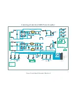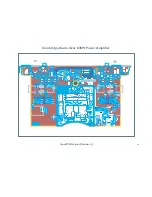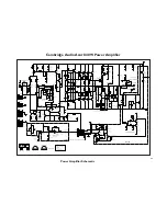
Cambridge Audio Azur 840W Power Amplifier
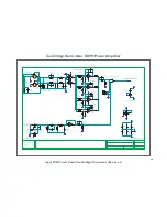
Input PCB Circuit Board (Audio Right) Schematic (Revision 1)
© COPYRIGHT
The Audio Partnership
Gallery Court
Hankey Place
LONDON SE1 4BB
Tel : +44 (0)171 940 2200
Fax : +44 (0)171 940 2233
DRAWN BY
CHECKED BY
DATE
DRAWING TITLE
E
G
A
P
.
o
N
G
N
I
W
A
R
D
SHEET TITLE
GENERAL NOTES
L Reid
15/07/08
AZUR 840W INPUT PCB
AUDIO RIGHT
4
/
2
4
/
8
5
5
0
2
P
A
1.
2.
3.
4.
5.
RIGHT INPUT
RIGHT OUTPUT
TOP: WHITE INSERT
BOTTOM: RED INSERT
+15V
-15V
GND
1
+
2
-
3
CN16
RIGHT OUTPUT
RIGHT INPUT
GND
1+G
+
2
-
3
4
CN17
5033T
Female XLR with Latch
BALANCED INPUT AMP
RIGHT CHAN
1.76 Vrms in for max output
1.57 Vrms in for max output
-3 dB @ 0.072 Hz
-3 dB @ 0.16 Hz
C100
100uF 16V
NP Electrolytic
C88
100uF 16V
NP Electrolytic
-15V
+15V
UNITY-GAIN OP MODULE DECOUPLE
C86
100nF 100V
Polypropylene
C87
100uF 35V
NP Electrolytic
C80
Met. Polyester
47nF 63V
C95
47nF 63V
Met. Polyester
C101
100nF 100V
Polypropylene
C89
100nF 100V
Polypropylene
C94
100nF 100V
Polypropylene
1
2
4
CN15:A
AV2-8.4-13EL
1
3
4
CN15:B
AV2-8.4-13EL
C92
1nF 50V
NP0 Ceramic
0805
+15V
-15V
R68
2R2
1/8W Metal Film
R70
2R2
1/8W Metal Film
+15V
-15V
+15V
-15V
R74
2R2
1/8W Metal Film
R76
2R2
1/8W Metal Film
-3 dB @ 0.072 Hz
C85
100nF 100V
Polypropylene
C84
100uF 35V
NP Electrolytic
C93
100uF 16V
NP Electrolytic
-3 dB @ 2.34 MHz
-3 dB @ 0.072 Hz
-3 dB @ 33.9 MHz
BAL INPUT
BAL/UNBAL INPUT SWITCH
SW2
Toggle switch
2
3
1
8
4
U14:A
NE5532D
6
5
7
U14:B
NE5532D
2
3
1
8
4
U13:A
NE5532D
6
5
7
U13:B
NE5532D
2
3
1
8
4
U11:A
NE5532D
6
5
7
U11:B
NE5532D
OPAMP DECOUPLE
-15V
+15V
C83
47nF 63V
Met. Polyester
C81
47nF 63V
Met. Polyester
C72
47nF 63V
Met. Polyester
C69
47nF 63V
Met. Polyester
C75
47nF 63V
Met. Polyester
C78
47nF 63V
Met. Polyester
R88
1k
0805 Thick Film
R86
22K
0805 Thick Film
R87
22K
0805 Thick Film
R91
0204 Melf
22K
R78
0204 Melf
750R
R83
0204 Melf
750R
R82
0204 Melf
750R
R84
0204 Melf
750R
R85
0204 Melf
750R
R81
0204 Melf
750R
R80
0204 Melf
750R
R79
0204 Melf
750R
C90
100pF 50V
0805 NP0 Ceramic
C91
100pF 50V
0805 NP0 Ceramic
C82
100pF 50V
0805 NP0 Ceramic
2
3
1
V+
10
V-
5
4
U12:A
Unity gain
8
7
9
V+
10
V-
5
6
U12:B
Unity gain
Rev 3: LK1 changed to 47R 1/8W; C88, C93 and C100 changed to 100uF 16V NP
C102
1nF 50V
NP0 Ceramic
0805
C104
100pF 50V
0805 NP0 Ceramic
C96
100pF 50V
0805 NP0 Ceramic
C97
100pF 50V
0805 NP0 Ceramic
R50
1k
0204 Melf
R53
1k
0204 Melf
R95
22k
0204 Melf
R97
22k
0204 Melf
R92
220k
0204 Melf
R93
220k
0204 Melf
R67
1k5
0204 Melf
R66
1k5
0204 Melf
C76
470pF 50V
NP0 0805
C77
470pF 50V
NP0 0805
C79
470pF 50V
NP0 0805
C74
470pF 50V
NP0 0805
C68
470pF 50V
NP0 0805
C73
470pF 50V
NP0 0805
C71
470pF 50V
NP0 0805
C70
470pF 50V
NP0 0805
R71
1k5
0204 Melf
R69
1k5
0204 Melf
R73
1k5
0204 Melf
R72
1k5
0204 Melf
R77
1k5
0204 Melf
R75
1k5
0204 Melf
R90
220K
0204 Melf
R3
100R
0204 Melf
1
2
3
CN1
3 Way
Straight Header
19
19
Summary of Contents for Azur 840W
Page 8: ...8 ...
Page 12: ...Cambridge Audio Azur 840W Power Amp Power PCB Layout 12 ...
Page 24: ...Cambridge Audio Azur 840W Power Amp Input PCB Layout 24 ...
Page 30: ...Cambridge Audio Azur 840W Power Amp Power Amp PCB Layout 30 ...
Page 34: ...Cambridge Audio Azur 840W Power Amp Control Bus PCB Schematic 34 ...
Page 38: ...Cambridge Audio Azur 840W Power Amp Mode Switch PCB Layout 38 ...
Page 39: ...Cambridge Audio Azur 840W Power Amplifier Mode Switch PCB Layout Revision 1 39 ...
Page 43: ...Cambridge Audio Azur 840W Power Amp On Standby Switch PCB Layout 43 ...

