background image

Title

Number

Revision

Size

A4

Date:

8-Mar-2010 

Sheet    of 

File:

D:\

电子设计

\AM10\AM10.DDB

Drawn By:

R50
100

C

80

47uF

/16V

C81
100P

SW1

TUNER

SW2

NC

SW4
CD

SW5

NC

SW7
DVD

SW8

MODE

SW10

PHONE

SW11

MP3/AUX

LED1

BLUE

1

2

3

REM1

REM1838

1

1

2

2

3

3

4

4

5

5

6

7

8

9

CON5B

9P-2.54

D1

1N4148

R74

10K

R75

10K

R76

10K

R77

10K

R78

10K

R79

10K

R80

10K

R81

10K

D2

1N4148

R8356K

REM

C

82

100

/16V

C

85

104

1

1

3

3

2

2

4

5

6

7

CON3B
7P-2.54

R84

0R

R85 4.7R

C

86

22uF

/16V

R86
100R

R87
100R

Z

D1

5

.6V

C84

104

R89

220R

C83
104

D-I/O

STB

DGND

+5V

T

O

 IN

P

U

B

OA

RD

T

O

 A

M

P

 B

OA

RD

AC1 2.5V

AC2 2.5V

+5V

1

1

2

2

3

3

4

4

5

5

CON2B
5P-2.5

1

1

2

2

3

3

4

4

5

5

CON2A
5P-2.54

GND

LHP

RHP

T

O

 PHON

ES

T

O

 PHON

ES

T

O

 M

P

3

 IN

F2

51

P17

48

P16

45

P15

44

1G

43

P14

41

10G

40

P13

37

P12

33

P11

32

8G

31

P10

29

7G

29

P9

26

6G

25

P8

22

P7

21

5G

20

P6

18

4G

17

P5

14

3G

13

P4

11

P3

8

P2

7

2G

6

9G

36

P1

4

F1

1

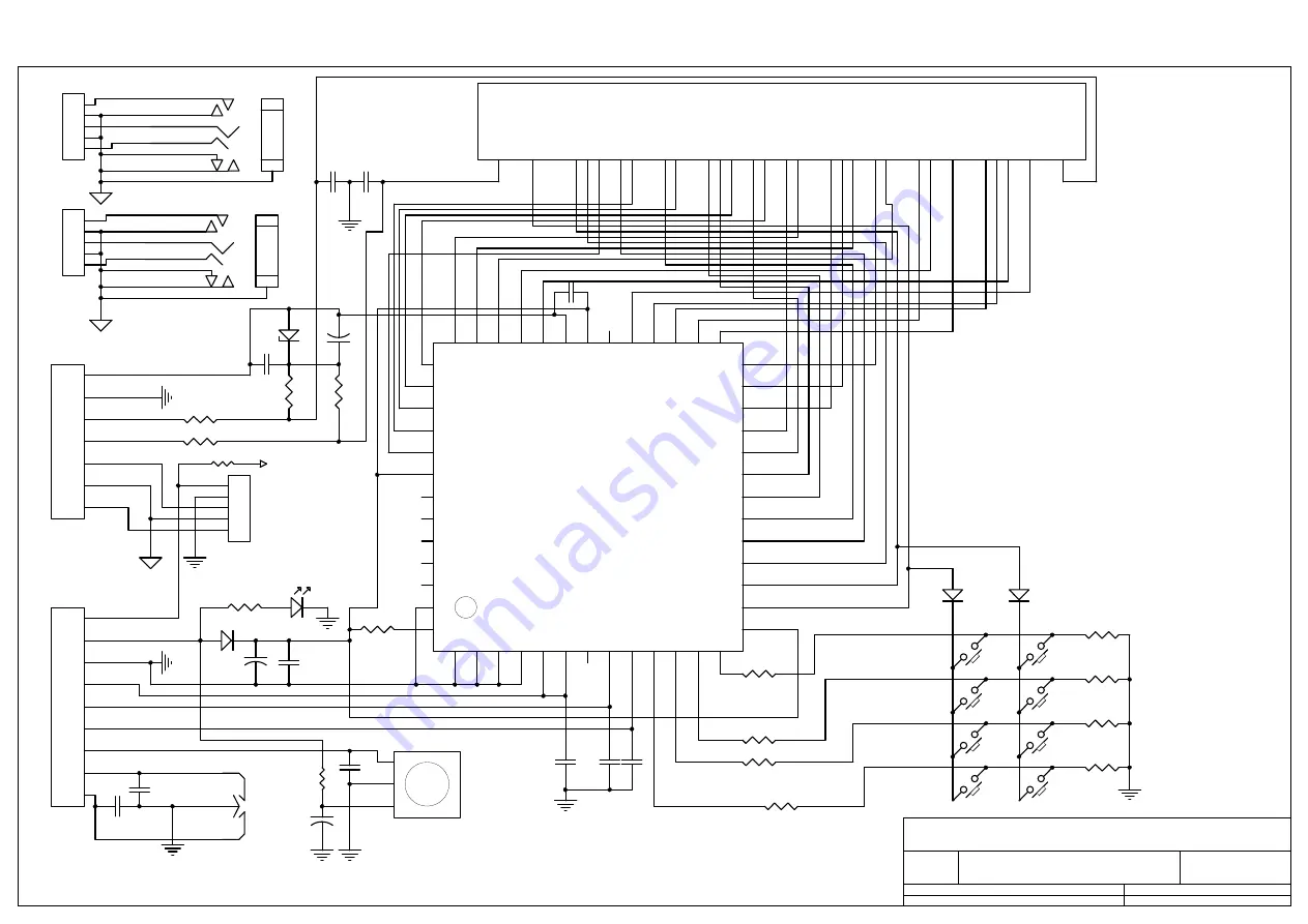
VFD1

VFD-10-BT-271NK

S

W1

1

S

W2

2

S

W3

3

S

W4

4

DOUT

5

D

IN

6

NC

7

CLK

8

S

TB

9

K1

10

K2

11

K3

12

K4

13

VDD

14

SG1/KS1

15

SG2/KS2

16

SG3/KS3

17

SG4/KS4

18

SG5/KS5

19

SG6KS6

20

SG7KS7

21

SG8KS8

22

SG9KS9

23

SG10KS10

24

SG11KS11

25

SG12KS12

26

G

R

16

27

G

R

15

28

G

R

14

29

G

R

13

30

G

R

12

31

G

R

11

32

VDD

33

V

EE

34

G

R

10

35

G

R9

36

G

R8

37

G

R7

38

G

R6

39

GR5

40

GR4

41

GR3

42

GR2

43

GR1

44

VDD

45

LED5

46

LED4

47

LED3

48

LED3

49

LED1

50

GND

51

OSC

52

U3

PTC6311

CLK

P13

P14

P15

P16

P17

DC3 -22V

C87
100P

C88

100P

EN1

EN2

1

2

3

4

5

7

8

JK2

M

IC

-I

N3

L IN

R IN

GND

DT

L-PH

R-PH

GND

R82

4.7K

GND

DT

L-PH

R-PH

GND

DT

1

1

2

2

3

3

4

4

5

5

CON1b
5P-2.54

1

2

3

4

5

7

8

JK1

M

P3

DT1

C

104

100P

C

105

100P

C

106

100P

C1

104

C2

104

D3

1N4007

1

2

3

SW9

SW-3P

P17

P16

P15

P14

P13

P1

P2

P3

P4

P5

P6

P7

P8

P9

P10

P11

P12

1G

2G

3G

4G

5G

6G

7G

8G

9G

10G

1G

2G

3G

4G

5G

6G

7G

8G

9G

10G

P1

P2

P3

P4

P5

P6

P7

P8

P9

P10

P11

P12

Topaz AM10 Service Manual

Amp PCB Schematic

12

Summary of Contents for Topaz AM10

Page 1: ...______________________ Specifications Topaz AM10 premium integrated amplifier Power Output 35 watts into 8 Ohms Frequency Response 3dB 5Hz 50kHz S N ref 1W 82dB unweighted THD unweighted 0 01 1kHz 80...

Page 2: ...____________________________________8 Main PCB Layout__________________________________________________________________ 9 Main PCB Schematic____________________________________________________________...

Page 3: ...lets or outlet grilles Do not cover the ventilation grilles with items such as newspapers tablecloths curtains etc This unit must not be used near water or exposed to dripping or splashing water or ot...

Page 4: ...ase consult your dealer for details Note The Ground terminals on both the record player and the AM10 should be connected where possible with a ground wire for lowest noise hum pickup Rec Out Connect t...

Page 5: ...the front panel to automatically re enable the Aux input Also note that as the output level of MP3 players tends to be quite low the AM10 adds 10dB to the current volume setting when and only when the...

Page 6: ...to the Topaz CD5 and CD10 user s manual Mute Mutes audio on the unit Press again to cancel mute Volume Increases or decreases the volume of the unit Also used to change the bass treble and balance se...

Page 7: ...Topaz AM10 Service Manual Exploded Diagram 7...

Page 8: ...14 Volume Encoder EC162102E1B HA1 FB TYPE D 4 PZ341 Volume pot 5 PZ415 Mains transformer 0 115V 230V OUT 24V 2 11V 2 3 6V 1 6 PZ420 AM10 Amp PCB assy complete 7 PZ416 Mains switch 5A 250V 1P1T P12 PRO...

Page 9: ...Topaz AM10 Service Manual Main PCB Layout 9...

Page 10: ...ramic 100nF 100V Lin Rin L1 24 5T 0 9mm Output Inductor L2 24 5T 0 9mm Output Inductor R27 2R2 2W Metal Film R28 2R2 2W Metal Film 1 2 3 4 CN2 4 Way Straight Header 1 2 3 4 5 6 7 CN3 7 Way Straight He...

Page 11: ...Topaz AM10 Service Manual Amp PCB Layout 11...

Page 12: ...18 4G 17 P5 14 3G 13 P4 11 P3 8 P2 7 2G 6 9G 36 P1 4 F1 1 VFD1 VFD 10 BT 271NK SW1 1 SW2 2 SW3 3 SW4 4 DOUT 5 DIN 6 NC 7 CLK 8 STB 9 K1 10 K2 11 K3 12 K4 13 VDD 14 SG1 KS1 15 SG2 KS2 16 SG3 KS3 17 SG4...

Page 13: ...Topaz AM10 Service Manual Input PCB Layout 13...

Page 14: ...VDD 56 Vref 57 R6 58 R1 59 R2 60 R3 61 R4 62 R5M 63 R5P 64 U1 LC75412 C68 1 50V R69 10K R70 10K C63 102 C64 102 C65 102 C66 102 C75 10 50V C59 10 25V C76 333 MUTE C13 4 7 50V C14 4 7 50V R13 1K R14 1K...

Page 15: ...Topaz AM10 Service Manual Mians PCB Layout 15...

Page 16: ...itical C1 C 1N 400V X1 Y1 CC 1nF 400V X1 Y1 Mains Rated Safety Critical J1 WIRE EYELET 250 120 J2 WIRE EYELET 250 120 SC1 FXG M3X10MM MC PH M3x10mm MC SC2 FXG M3X10MM MC PH M3x10mm MC WS1 FXG M3 NUT M...

Page 17: ...itor M C PEI 822 63V J 2 C42 C41 073 00012 000 Crystal 12 000MHZ 30PPM 49S 1 X1 053 24C02 001 IC EEPROM AT24C02 DIP8 ATMEL 1 U7 053 0AM10 001 IC MCU AM10 AT89C2051 DIP20 1 U2 PZ409 053 05532 001 IC OP...

Page 18: ...50V Ceramic 1 C38 10 5mm Pitch 16 10nF 50V Ceramic 1 C41 10 2 5mm Pitch 17 100nF 50V Mono Ceramic 10 C7 C9 C11 C13 C15 C18 C20 C39 C42 10 5mm Pitch 18 100nF 100V Mono Ceramic 2 C26 C32 10 5mm Pitch 19...

Page 19: ...used INDUCTORS 41 24 5T 0 9mm Output Inductor 2 L1 L2 Through Hole AP13772 1 42 24AWG Tinned Link Wire 1 L3 Inductor silk is on PCB for unit EMC testing INTEGRATED CIRCUITS 43 8V 1A Regulator 1 U1 790...

Reviews: