•
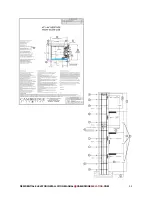
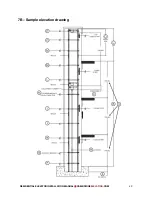
The overhead is correct, refer to
sample elevation diagram 7B
note: C.
•
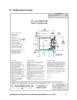
The shaft width is correct at each landing, refer to
sample layout diagram 7A
note: A.
•
The shaft depth is correct at each landing, refer to
sample layout diagram 7A
note: B
•
The shaft walls are plumb and true
•
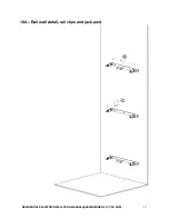
The rail wall construction is per specifications, refer to
sample layout diagram 7A
note:
C
•
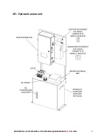
The location of the controller and power unit is as per plan, refer to
sample layout
diagram 7A
note: D
•
The 220 and 120 power plugs are or will be installed within 3 feet of the right side of the
main controller’s location,
diagram 23A
Controller and HPU detail
•
The rough door openings at each landing are inline and the correct size and framed with
2X4 lumber.
•
If the landing door wall is made with 2x6 lumber, the door will either need to be inset or
a door ba
ffl
e will need to be installed.
•
Swing door openings should typically be 2 inches wider then the door width and 2
½
inches higher.
o
Note: some door frames could require wider rough openings.
•
For heritage models the landing door width should match the cab door width. Example
a 32 inch cab door should have a 32 inch landing door.
•
Cambrian landing openings should be at least 46 inches wide but we recommend
leaving the full width of the shaft open and framing up to the landing frame after it is
installed.
•
Cambrian landing headers should be
o
90 inches high for 2000mm high doors
o
96 inches high for 2150mm fire rated doors
o
106 inches high for 2400 mm high doors
•
The pit is or will be free from debris and liquids, clean and level.
•
Establish a path for the cylinder and sling to get into the hoistway
o
Note: In some cases, the cylinder may need to be placed in or near the
shaft at an earlier stage of construction or craned into place.
Contact your sales engineer or technical support (1-800-265-3579) at Cambridge Elevating as
soon as possible if any of the measurements or details vary from the final diagrams. Have the
exact measurements ready when you call and we will check to see if any of the site di
ff
erences
will a
ff
ect your installation.
RESIDENTIAL ELEVATOR INSTALLATION MANUAL CAMBRIDGE
ELEVATING
.COM
33
Summary of Contents for BES 3
Page 1: ...BES 3 RESIDENTIAL ELEVATOR INSTALLATION MANUAL OCTOBER 2019...
Page 18: ...3B Overview of rail wall RESIDENTIAL ELEVATOR INSTALLATION MANUAL CAMBRIDGEELEVATING COM 17...
Page 20: ...3D Hydraulic power unit RESIDENTIAL ELEVATOR INSTALLATION MANUAL CAMBRIDGEELEVATING COM 19...
Page 35: ...RESIDENTIAL ELEVATOR INSTALLATION MANUAL CAMBRIDGEELEVATING COM 34...
Page 40: ...7A Sample layout drawing RESIDENTIAL ELEVATOR INSTALLATION MANUAL CAMBRIDGEELEVATING COM 39...
Page 41: ...7B Sample elevation drawing RESIDENTIAL ELEVATOR INSTALLATION MANUAL CAMBRIDGEELEVATING COM 40...
Page 43: ...RESIDENTIAL ELEVATOR INSTALLATION MANUAL CAMBRIDGEELEVATING COM 42...
Page 49: ...RESIDENTIAL ELEVATOR INSTALLATION MANUAL CAMBRIDGEELEVATING COM 48...
Page 57: ...RESIDENTIAL ELEVATOR INSTALLATION MANUAL CAMBRIDGEELEVATING COM 56...
Page 58: ...13A Jack post detail RESIDENTIAL ELEVATOR INSTALLATION MANUAL CAMBRIDGEELEVATING COM 57...
Page 61: ...14A Cylinder detail RESIDENTIAL ELEVATOR INSTALLATION MANUAL CAMBRIDGEELEVATING COM 60...
Page 65: ...16A Sling RESIDENTIAL ELEVATOR INSTALLATION MANUAL CAMBRIDGEELEVATING COM 64...
Page 70: ...RESIDENTIAL ELEVATOR INSTALLATION MANUAL CAMBRIDGEELEVATING COM 69...
Page 74: ...20A Sheave detail RESIDENTIAL ELEVATOR INSTALLATION MANUAL CAMBRIDGEELEVATING COM 73...
Page 76: ...21A Sling roping detail RESIDENTIAL ELEVATOR INSTALLATION MANUAL CAMBRIDGEELEVATING COM 75...
Page 84: ...24A Pre stroke detail RESIDENTIAL ELEVATOR INSTALLATION MANUAL CAMBRIDGEELEVATING COM 83...
Page 87: ...26A Jack post roping detail RESIDENTIAL ELEVATOR INSTALLATION MANUAL CAMBRIDGEELEVATING COM 86...
Page 89: ...27A Sling extensions detail RESIDENTIAL ELEVATOR INSTALLATION MANUAL CAMBRIDGEELEVATING COM 88...
Page 91: ...28A Sling roller detail RESIDENTIAL ELEVATOR INSTALLATION MANUAL CAMBRIDGEELEVATING COM 90...
Page 93: ...29A Cab floor RESIDENTIAL ELEVATOR INSTALLATION MANUAL CAMBRIDGEELEVATING COM 92...
Page 105: ...34A Cab inline RESIDENTIAL ELEVATOR INSTALLATION MANUAL CAMBRIDGEELEVATING COM 104...
Page 106: ...34B Cab through RESIDENTIAL ELEVATOR INSTALLATION MANUAL CAMBRIDGEELEVATING COM 105...
Page 107: ...34C Cab 90 degree RESIDENTIAL ELEVATOR INSTALLATION MANUAL CAMBRIDGEELEVATING COM 106...
Page 112: ...36A Hoistway wiring detail RESIDENTIAL ELEVATOR INSTALLATION MANUAL CAMBRIDGEELEVATING COM 111...
Page 115: ...37A Cartop electrical RESIDENTIAL ELEVATOR INSTALLATION MANUAL CAMBRIDGEELEVATING COM 114...
Page 121: ...39A Sensor head RESIDENTIAL ELEVATOR INSTALLATION MANUAL CAMBRIDGEELEVATING COM 120...
Page 122: ...39B Coded strips RESIDENTIAL ELEVATOR INSTALLATION MANUAL CAMBRIDGEELEVATING COM 121...
Page 127: ...40A TRAVEL CABLE RESIDENTIAL ELEVATOR INSTALLATION MANUAL CAMBRIDGEELEVATING COM 126...
Page 129: ...41A Control panel diagram RESIDENTIAL ELEVATOR INSTALLATION MANUAL CAMBRIDGEELEVATING COM 128...
Page 163: ...RESIDENTIAL ELEVATOR INSTALLATION MANUAL CAMBRIDGEELEVATING COM 162...
Page 164: ...RESIDENTIAL ELEVATOR INSTALLATION MANUAL CAMBRIDGEELEVATING COM 163...
Page 165: ...RESIDENTIAL ELEVATOR INSTALLATION MANUAL CAMBRIDGEELEVATING COM 164...
Page 166: ...RESIDENTIAL ELEVATOR INSTALLATION MANUAL CAMBRIDGEELEVATING COM 165...
Page 167: ...RESIDENTIAL ELEVATOR INSTALLATION MANUAL CAMBRIDGEELEVATING COM 166...
Page 171: ...RESIDENTIAL ELEVATOR INSTALLATION MANUAL CAMBRIDGEELEVATING COM 170...
Page 172: ...RESIDENTIAL ELEVATOR INSTALLATION MANUAL CAMBRIDGEELEVATING COM 171...
Page 173: ...RESIDENTIAL ELEVATOR INSTALLATION MANUAL CAMBRIDGEELEVATING COM 172...
Page 174: ...RESIDENTIAL ELEVATOR INSTALLATION MANUAL CAMBRIDGEELEVATING COM 173...
Page 175: ...RESIDENTIAL ELEVATOR INSTALLATION MANUAL CAMBRIDGEELEVATING COM 174...
Page 187: ...49A Handrail RESIDENTIAL ELEVATOR INSTALLATION MANUAL CAMBRIDGEELEVATING COM 186...
Page 205: ...57A Telephone line detail RESIDENTIAL ELEVATOR INSTALLATION MANUAL CAMBRIDGEELEVATING COM 204...

