background image

Procedure:

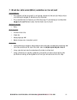
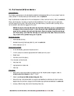
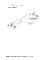
Attach the first rail (M2) to the baseplate (M8) with the rail clips (M3-C) hand tight

If the first rail is a full rail (M2-A) or a cut rail (M2-B) long enough that it passes a rail 
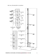
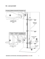
bracket (M3-A), refer to the rail wall detail diagram note: A

o

Attach the rail (M2) to the rail bracket (M3-A) with rail clips (M3-C), hand tight.

o

Measure the distance from the center of the rail face to the front of the rail 
bracket (M3-A) 

o

Adjust the above measurement to 5 inches

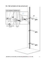
, refer to the 

rail wall detail 

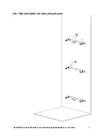
diagram 10a

 note: B

o

Tighten the rail clips (M3-C) at the rail bracket (M3-A)

o

Plumb the rail (M2) using the 5-foot level placed on the front and the side of the 
rail

o

Shift the baseplate (M8) if necessary, so that the rail (M2) is plumb and true

o

Tighten the rail clips (M3-C) at the baseplate (M8), and confirm the rail is still 

plumb in both directions

o

Repeat the above steps for any other brackets the first rail passes

If the first rail did not pass a rail bracket (M3-A) 

o

Attach the first rail (M2) to the second with a splice plate (M2-C) and hardware 
(M2-CH), refer to 

rail wall detail diagram 10a

 note: F

o

Use the long level on the front and side faces of the rail to ensure it is true

o

Tighten the splice plate hardware (M2-CH) , and confirm the rail is till true

o

Attach the second rail to the first rail bracket (M3-A) with rail clips (M3-C), hand 
tight, refer to 

rail wall detail diagram 10a

 note: G

o

Measure the distance from the center of the rail face to the front of the rail 
bracket (M3-A) 

o

Adjust the above measurement to 5 inches

, refer to 

rail wall detail diagram 

10a

 note: B

o

Tighten the rail clips (M3-C) at the bracket

o

Check that the rail is running true by checking for plumb on each face of the rail 
using the long level 

o

Shift the baseplate (M8) if necessary, so that the rail is plumb and true

o

Tighten the rail clips (M3-C) at the baseplate (M8) 

o

Repeat the above steps for any other brackets the rails pass

RESIDENTIAL ELEVATOR INSTALLATION MANUAL   CAMBRIDGE

ELEVATING

.COM


51

Summary of Contents for BES 3

Page 1: ...BES 3 RESIDENTIAL ELEVATOR INSTALLATION MANUAL OCTOBER 2019...

Page 2: ...d require your feedback to help make this manual as complete and user friendly as possible Whether you have a better method for a particular task or advice to new installers find something missing hav...

Page 3: ...rail clip assembly detail f Limit switch cam rail clip assembly detail 5 Pre install site check Objective Running sling 6 Move material into the building 7 Mark the rail bracket M3 A centerline on the...

Page 4: ...he wire ropes to the sling a Sling roping detail 22 Install the controller and hydraulic power unit a Controller and hydraulic power unit detail 23 Bleeding the cylinder a Cylinder bleed screw detail...

Page 5: ...1 a Cab to sling attachment 36 Hoistway wiring E11 and E7 a Hoistway wiring detail 37 Installing the cartop electrical a Cartop electrical b Slack rope switch detail 38 Install the Cab Operating Panel...

Page 6: ...4 inch cab c 2 speed operator with doors the same height as the cab d 3 speed operator with doors the same height as the cab e 2 speed operator with 78 inch doors on a 96 inch cab f 3 speed operator w...

Page 7: ...Line rupture valve detail 56 Setting and testing the pressure relief valve PRV a Blain valve detail 57 Testing the telephone a Telephone line detail 58 Power fail test 59 Final inspection 60 Customer...

Page 8: ...it P 3 phase power unit Q 120AC lighting R Travel cable junction boxes S Special call stations T Special COP options U Bi fold gate operator V Landing swing door operator interface W 3rd party control...

Page 9: ...inch o 5 8th inch Screwdrivers o 1 16 inch slot 6 inches long o stubby No 2 Philips screwdriver star Battery powered screwdriver Bits for a power screwdriver o 2 Philips star o 2 Robertson square Wren...

Page 10: ...track to length Angle grinder or saw to cut ropes Shop type vacuum Dustpan and brush Broom Coal chisel Metal shims Way to lift rails safely Rail files Chain fall or electric hoist recommended for long...

Page 11: ...concrete bits For hard pipe o Pipe wrenches o Pipe threader cutter For Cambrian Landing doors o Heavy duty cable crimpers May be required for shortening lengthening diagnosing or repairing cables and...

Page 12: ...wall 4 to 6 to inch long 8 wood screws to attach travel cable clamp to the cartop Two sided tape Screws to mount gate operator Cable ties small and large Tie wrap anchors A mild cleaner appropriate f...

Page 13: ...urs of delivery Report any damage to Cambridge Elevating that was not noticed when the elevator was delivered as soon as it is found and any missing parts within a week of delivery The packing list wi...

Page 14: ...ARE KIT 4 35 C7 H HANDRAIL HARDWARE INCLUDED 49 C8 CARTOP BOX 37 E1 MAIN CONTROLLER ASSEMBLY 22 E2 MAIN CONTROLLER 22 E2 A MAIN CONTROLLER TO TANK BRACKET 22 E2 B MAIN CONTROLLER TO TANK HARWARE 22 E2...

Page 15: ...14 23 24 H1 HYDRAULIC CYLINDER INC BOLT AND FITTING 14 19 20 H1 A HYDRAULIC POWER UNIT 22 33 51 52 53 H2 DRAIN LINE 19 H3 HOSE AND FITTING ASSEMBLY 4 H4 HYDRAULIC HOSE 4 18 H4 A HYDRAULIC FITTINGS 4...

Page 16: ...A ROPE CLIPS 21 26 M6 B SHACKLES 26 M6 C SHACKLE HEARTS 21 26 M6 D JACK POST ASSEMBLY 13 M7 JACK POST TOPPER 4 13 M7 A JACK POST U BOLT SQUARE HARDWARE INC 13 M7 B JACK POST 13 M7 C SPACER THIN 13 14...

Page 17: ...HANEL HARDWARE KIT M13 H REGULAR CODED STRIP 4 39 M21 TOP FLOOR CODED STRIP 4 39 M22 LIMIT SWITCH ASSEMBLY 37 M31 LIMIT SWITCH CAM ASSEMBLY 4 M32 LIMIT SWITCH CAM 4 M32 A RESIDENTIAL ELEVATOR INSTALLA...

Page 18: ...3B Overview of rail wall RESIDENTIAL ELEVATOR INSTALLATION MANUAL CAMBRIDGEELEVATING COM 17...

Page 19: ...3C Overview of rail wall with cab RESIDENTIAL ELEVATOR INSTALLATION MANUAL CAMBRIDGEELEVATING COM 18...

Page 20: ...3D Hydraulic power unit RESIDENTIAL ELEVATOR INSTALLATION MANUAL CAMBRIDGEELEVATING COM 19...

Page 21: ...3E Sample packing list page 1 RESIDENTIAL ELEVATOR INSTALLATION MANUAL CAMBRIDGEELEVATING COM 20...

Page 22: ...3E Sample packing list page 2 RESIDENTIAL ELEVATOR INSTALLATION MANUAL CAMBRIDGEELEVATING COM 21...

Page 23: ...3E Sample packing list page 3 RESIDENTIAL ELEVATOR INSTALLATION MANUAL CAMBRIDGEELEVATING COM 22...

Page 24: ...3E Sample packing list page 4 RESIDENTIAL ELEVATOR INSTALLATION MANUAL CAMBRIDGEELEVATING COM 23...

Page 25: ...the line rupture valve H5 Material required Jack post top M7 A 2 wedge sockets Shackles M6 C Rail clips M3 C Cartop sling mounting brackets C7 A Sling mounting kit C7 H Top limit switch cam M32 Botto...

Page 26: ...spirits may be required o Check the rails for any damage to the machined surfaces tongues grooves and resolve any issues Preassembling jack post top M7 A o Remove the cotter pins from the two shackle...

Page 27: ...draulic system clean Any debris that gets into a hose or connector will find its way into the hydraulic valve and likely cause problems with the valve o Place the line rupture valve in a vise o Refer...

Page 28: ...4A Jack post top detail M7 A 4B Rail clip detail M3 A B RESIDENTIAL ELEVATOR INSTALLATION MANUAL CAMBRIDGEELEVATING COM 27...

Page 29: ...4C Cab to sling mount assembly detail RESIDENTIAL ELEVATOR INSTALLATION MANUAL CAMBRIDGEELEVATING COM 28...

Page 30: ...4D Line rupture valve assembly detail RESIDENTIAL ELEVATOR INSTALLATION MANUAL CAMBRIDGEELEVATING COM 29...

Page 31: ...4E Coded strip rail clip assembly detail RESIDENTIAL ELEVATOR INSTALLATION MANUAL CAMBRIDGEELEVATING COM 30...

Page 32: ...4F Limit switch cam rail clip assembly detail RESIDENTIAL ELEVATOR INSTALLATION MANUAL CAMBRIDGEELEVATING COM 31...

Page 33: ...ic hose are to be ran inside conduit or sleeves or walls note the following The travel cable is nearly 3 inches wide and will not pull through tight bends or multiple bends very well 4 inch or larger...

Page 34: ...frames could require wider rough openings For heritage models the landing door width should match the cab door width Example a 32 inch cab door should have a 32 inch landing door Cambrian landing ope...

Page 35: ...RESIDENTIAL ELEVATOR INSTALLATION MANUAL CAMBRIDGEELEVATING COM 34...

Page 36: ...material is distributed Hydraulic lines may be 1 or more hoses hard pipe or a combination of the two This procedure will assume the project is using 1 or 2 hydraulic lines In many cases it is better...

Page 37: ...t U bolt assembly M7 B o Line rupture valve with fittings and hose H5 H4 A H4 B o Installer s remote pendant E38 Bring material to the machine room location o Hydraulic power unit H2 o Hydraulic hose...

Page 38: ...efer to elevation diagram o 1 bag of rail bracket mounting hardware M3 H per rail bracket M3 A o 4 rail clips M3 C per rail bracket o Possibly cylinder bracket and spacer if 70mm or 80mm cylinder RESI...

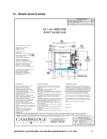
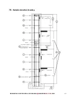
Page 39: ...ols required Plumb bob and line Chalk line Measuring tape 25ft Black sharpie and a carpenter s pencil Procedure Use the final layout diagram measurement of the rail system centerline to determine and...

Page 40: ...7A Sample layout drawing RESIDENTIAL ELEVATOR INSTALLATION MANUAL CAMBRIDGEELEVATING COM 39...

Page 41: ...7B Sample elevation drawing RESIDENTIAL ELEVATOR INSTALLATION MANUAL CAMBRIDGEELEVATING COM 40...

Page 42: ...er rail brackets the play in the slots will allow you to make up for minor fluctuations in the rail wall without shimming Options for fastening rail brackets M3 A to the rail wall and typical recommen...

Page 43: ...RESIDENTIAL ELEVATOR INSTALLATION MANUAL CAMBRIDGEELEVATING COM 42...

Page 44: ...iers should be used in front of open doorways and unsecured doors Communication with fellow workers is critical to working safely together but especially when they are directly above below you Applica...

Page 45: ...kets should be shimmed out if necessary such that the rail clips are centered in the slots Failure to do this may result in the cylinder being out of plumb Materials required Rail brackets M3 A Bracke...

Page 46: ...the distance measured within a of an inch If the distance is more then 7 inches than the bottom bracket will need to be shimmed out The shim required would be the distance measured minus 7 inches wit...

Page 47: ...o Shim as necessary to achieve this Remove the plumb lines RESIDENTIAL ELEVATOR INSTALLATION MANUAL CAMBRIDGEELEVATING COM 46...

Page 48: ...10A Rail wall detail rail clips and jack post RESIDENTIAL ELEVATOR INSTALLATION MANUAL CAMBRIDGEELEVATING COM 47...

Page 49: ...RESIDENTIAL ELEVATOR INSTALLATION MANUAL CAMBRIDGEELEVATING COM 48...

Page 50: ...will sit is flat and smooth Set the cylinder baseplate M8 directly under the bottom rail bracket M3 A refer to rail wall detail diagram 12a note E Check that the baseplate M8 is sitting level side to...

Page 51: ...ale end should always face up refer to rail wall detail diagram 10a note F The protective coating can be removed from the rails before they are installed As the rails are being fitted together check t...

Page 52: ...e first rail passes If the first rail did not pass a rail bracket M3 A o Attach the first rail M2 to the second with a splice plate M2 C and hardware M2 CH refer to rail wall detail diagram 10a note F...

Page 53: ...ket M3 A is maintained Repeat the above 3 steps until you reach the top of the shaft Once you reach the top o Go back over the entire rail with the long level and make fine adjustments if necessary o...

Page 54: ...12A Rail wall detail rail clips and jack post RESIDENTIAL ELEVATOR INSTALLATION MANUAL CAMBRIDGEELEVATING COM 53...

Page 55: ...Install the jack post M7 C inside the angled pieces on the baseplate M8 refer to cylinder jack post detail diagram 13a note A Place the jack post top onto the jack post making sure it is oriented corr...

Page 56: ...M7 to the rail brackets M3 A is maintained RESIDENTIAL ELEVATOR INSTALLATION MANUAL CAMBRIDGEELEVATING COM 55...

Page 57: ...RESIDENTIAL ELEVATOR INSTALLATION MANUAL CAMBRIDGEELEVATING COM 56...

Page 58: ...13A Jack post detail RESIDENTIAL ELEVATOR INSTALLATION MANUAL CAMBRIDGEELEVATING COM 57...

Page 59: ...mm cylinders part numbers start with 304 For all other cylinders refer to option D and E Material required Hydraulic cylinder H1 Round U bolt with nuts and washers M4 B If your cylinder is an OLS 70 o...

Page 60: ...Attach the U bolt M4 B to the bracket with the supplied nuts and washers hand tight Check that the cylinder H1 is true plumb side to side and front to back using the long level shift if necessary Conf...

Page 61: ...14A Cylinder detail RESIDENTIAL ELEVATOR INSTALLATION MANUAL CAMBRIDGEELEVATING COM 60...

Page 62: ...e out as far as they can come and lock them in place with two sets of vice grips This will disengage the safeties brakes and allow the sling to slide onto the rails Refer to sling detail diagram 15a n...

Page 63: ...15A Sling with roller detail RESIDENTIAL ELEVATOR INSTALLATION MANUAL CAMBRIDGEELEVATING COM 62...

Page 64: ...ll the bolts with their holes Materials required Sling cross piece M1 B Sling hardware kit included M1 BH Tools recommended inch wrenches 2 inch socket with driver Procedure Set the sling extension M1...

Page 65: ...16A Sling RESIDENTIAL ELEVATOR INSTALLATION MANUAL CAMBRIDGEELEVATING COM 64...

Page 66: ...dware M3 CH Tools recommended 18 to 20V Battery powered impact wrench inch socket inch wrenches Rags Gloves Rail files Long level Procedure Note You will need to lower the first and possibly the secon...

Page 67: ...clips M3 C at the baseplate M8 Attach a splice plate M2 C to the top of the last rail M2 Attach the next rail M2 to the previous Attach the rail M2 to the rail bracket M3 A with rail clips M3 C as yo...

Page 68: ...to the hydraulic valve and will cause internal leakage issues later on Please keep caps on the hose pipe ends and fittings until they are required and clean everything as you go with lint free clothe...

Page 69: ...H5 is on your right and almost touching the rail wall In this position the LRV will clear the sling M1 shackles M6 C and safeties Tighten the U bolt M4 B holding the cylinder H1 with a 9 16th inch wre...

Page 70: ...RESIDENTIAL ELEVATOR INSTALLATION MANUAL CAMBRIDGEELEVATING COM 69...

Page 71: ...ight angled connector that comes attached to the top of the cylinder 2 Liter plastic jug optional not supplied Tools recommended Knife to cut plastic line Appropriate tools for clips you are using Pro...

Page 72: ...19A Hydraulic drain line detail RESIDENTIAL ELEVATOR INSTALLATION MANUAL CAMBRIDGEELEVATING COM 71...

Page 73: ...sheave between the rails loosening the shoe brackets as necessary Lower the sheave onto the thick bottom sheave plate Reattach the thick bottom sheave plate to the sheave with the hardware you set asi...

Page 74: ...20A Sheave detail RESIDENTIAL ELEVATOR INSTALLATION MANUAL CAMBRIDGEELEVATING COM 73...

Page 75: ...the shackles M6 C on the sling refer to diagram 21A Run the ropes M6 A into the shackles M6 C and out the bottom making sure not to cross the ropes refer to sling roping detail diagram 21A Place a hea...

Page 76: ...21A Sling roping detail RESIDENTIAL ELEVATOR INSTALLATION MANUAL CAMBRIDGEELEVATING COM 75...

Page 77: ...2 for service calls Note It is very important that contamination metal filings dirt and dust be kept out of the oil and fittings Make sure the top of the buckets funnels and fittings are clean before...

Page 78: ...ne room in most jurisdictions and helps with the transmission of vibrations to the pipe Note a 90 degree fitting is provided and may be used here to turn the hose quicker in towards the wall Open the...

Page 79: ...ler board just below the fuses that will turn o the high speed valves This can be advantageous when fine tuning the pump adjustments ringing out the cylinder and roping the sling RESIDENTIAL ELEVATOR...

Page 80: ...22A Controller and hydraulic power unit detail RESIDENTIAL ELEVATOR INSTALLATION MANUAL CAMBRIDGEELEVATING COM 79...

Page 81: ...air out and then repeat above Tip stand to one side with a rag ready to go as oil will come out when the air stops As the oil moves into the top of the cylinder the pitch of the sound will increase S...

Page 82: ...23A Cylinder bleed screw detail RESIDENTIAL ELEVATOR INSTALLATION MANUAL CAMBRIDGEELEVATING COM 81...

Page 83: ...a measuring tape up to measure the distance between the top of the cylinders casing and the bottom of the sheave plate refer to the pre stroke detail diagram 25a Stop when the distance between the to...

Page 84: ...24A Pre stroke detail RESIDENTIAL ELEVATOR INSTALLATION MANUAL CAMBRIDGEELEVATING COM 83...

Page 85: ...erence between the thickness of flooring going into the cab and onto the landing Be sure to account for any material that will be in between the rough floor and the finished floor Remove the vise gri...

Page 86: ...ches of travel o Install the cotter pins and bend over the ends Run the ropes M6 into the shackles and out the bottom making sure not to cross the ropes refer to jack post roping detail diagram 27a Pl...

Page 87: ...26A Jack post roping detail RESIDENTIAL ELEVATOR INSTALLATION MANUAL CAMBRIDGEELEVATING COM 86...

Page 88: ...tion to the proper procedures The objective is for the center of the large slots through which the threaded rod will go to end up 1 5 inches above the cab s ceiling Interior cab height floor thickness...

Page 89: ...27A Sling extensions detail RESIDENTIAL ELEVATOR INSTALLATION MANUAL CAMBRIDGEELEVATING COM 88...

Page 90: ...gram 30a Shift the sling until it is straight and centered by ensuring the inside edge of the rollers are flush with the inside face of the rails Tighten the four side rollers until they touch the rai...

Page 91: ...28A Sling roller detail RESIDENTIAL ELEVATOR INSTALLATION MANUAL CAMBRIDGEELEVATING COM 90...

Page 92: ...other walls Mark the centerline for the landing doors M10 on the cab floor as per the final layout diagram Use the centerlines to check the position of the bottom floor landing doors M10 if they are...

Page 93: ...29A Cab floor RESIDENTIAL ELEVATOR INSTALLATION MANUAL CAMBRIDGEELEVATING COM 92...

Page 94: ...e no tension on the cables This is accomplished by adjusting the nuts at the ends of each cables sheath to change the tension of the cable inside Set each block so there is a 1 16th inch gap between t...

Page 95: ...30A Adjusting the safeties brakes RESIDENTIAL ELEVATOR INSTALLATION MANUAL CAMBRIDGEELEVATING COM 94...

Page 96: ...n the two bolts hold it with a 7 16th inch wrench and reposition it Use the remote to move the sling up a foot o the pit floor Place blocking under the sling that is around six inches high such that i...

Page 97: ...31A Adjusting the safeties brakes RESIDENTIAL ELEVATOR INSTALLATION MANUAL CAMBRIDGEELEVATING COM 96...

Page 98: ...ng the sling any temporary platforms ladders or metal staging will need to be removed Materials required None Tools recommended Depends on the method used Procedure Depends on the method used RESIDENT...

Page 99: ...board E2 to OFF Using the remote carefully move the platform up and down the shaft documenting the following o The setback at each landing o The clearance to other walls If any of the measurements ar...

Page 100: ...cument any measurements that di er from your projects final drawings and call technical support Lower the sling down into the pit and confirm the distance between the cab floor and the landing floor a...

Page 101: ...ls include Full wall Return wall Bulkhead only Return wall with bulkhead attached No wall For cabs with only one gate opening each full wall is marked on the outside with a sticker stating one of the...

Page 102: ...in place through the floor with 4 of the bolts these may be longer if the floor is thicker than typical Note Washers are to be used when a bolt or nut is up against the wood Bolt between adjoining wa...

Page 103: ...wood Install the remaining bolts between walls 3 inches below and 17 inches below the ceiling hand tight Cab with two openings next to each other known as a 90 degree cab Bring each full wall into th...

Page 104: ...with 4 bolts provided Note Washers are to be used when a bolt head or nut is up against the wood Install the remaining bolts between walls 3 inches below and 17 inches below the ceiling hand tight Che...

Page 105: ...34A Cab inline RESIDENTIAL ELEVATOR INSTALLATION MANUAL CAMBRIDGEELEVATING COM 104...

Page 106: ...34B Cab through RESIDENTIAL ELEVATOR INSTALLATION MANUAL CAMBRIDGEELEVATING COM 105...

Page 107: ...34C Cab 90 degree RESIDENTIAL ELEVATOR INSTALLATION MANUAL CAMBRIDGEELEVATING COM 106...

Page 108: ...35A Connect the two cab mount brackets C7 A to the two sling extensions M1 C using the provided hardware C7 H as per diagram 35A and tighten fully The location of the cab mounting bracket C7 should be...

Page 109: ...35A Cab to sling attachment RESIDENTIAL ELEVATOR INSTALLATION MANUAL CAMBRIDGEELEVATING COM 108...

Page 110: ...ocks E10 for Elmira and Heritage landings Cambrian breakout box for Cambrian landings Clips to attach wiring to the wall of the shaft not included Blue Cat5 cables E11 one per call station White Cat5...

Page 111: ...the call station and interlock and temporarily mount them inside the shaft or leave the cables coiled up in the corner of the shaft and install the locks and call stations later o Screw the call stat...

Page 112: ...36A Hoistway wiring detail RESIDENTIAL ELEVATOR INSTALLATION MANUAL CAMBRIDGEELEVATING COM 111...

Page 113: ...e coming out of one side for a single gate cab Note The cartop box is equipped with strain relief bars where the cables exit the box The screws can be loosened and the bars removed until the wiring is...

Page 114: ...plugs on the circuit board Each cable is labelled either upper lower or coded door zone o The sensor head needs to engage the coded strips and can be configured as left handed or right handed o Tempo...

Page 115: ...37A Cartop electrical RESIDENTIAL ELEVATOR INSTALLATION MANUAL CAMBRIDGEELEVATING COM 114...

Page 116: ...37B Slack rope switch detail RESIDENTIAL ELEVATOR INSTALLATION MANUAL CAMBRIDGEELEVATING COM 115...

Page 117: ...the side of the COP box with the cage nuts in the COP mounting brackets and install the four bolts and washers E3 H hand tight See diagram 38A Position the COP box at the correct depth the edge of th...

Page 118: ...38A Cab Operating Panel COP RESIDENTIAL ELEVATOR INSTALLATION MANUAL CAMBRIDGEELEVATING COM 117...

Page 119: ...The other coded strips have a 6 5 inch floor zone window centered in the middle of the strip The top limit switch needs to activate when the cab is 1 to 3 inches above the top floor However it is best...

Page 120: ...procedures applicable to your situation Attach the bottom limit cam M32 using the rail clips M3 C at the BLC mark o Bottom and mid floor coded strips With the cab at floor level measure and mark CS on...

Page 121: ...39A Sensor head RESIDENTIAL ELEVATOR INSTALLATION MANUAL CAMBRIDGEELEVATING COM 120...

Page 122: ...39B Coded strips RESIDENTIAL ELEVATOR INSTALLATION MANUAL CAMBRIDGEELEVATING COM 121...

Page 123: ...39C Coded strips and limit switch cams RESIDENTIAL ELEVATOR INSTALLATION MANUAL CAMBRIDGEELEVATING COM 122...

Page 124: ...39D Coded strips and Limit switch cams relationship RESIDENTIAL ELEVATOR INSTALLATION MANUAL CAMBRIDGEELEVATING COM 123...

Page 125: ...crews to attach the clamp to the cartop not included Tools recommended Screwdriver for screws above Procedure Bring the travel cable package E5 to the cartop Screw one of the travel cable clips E5 B t...

Page 126: ...e Fold the cable to make a 90 degree bend down and through the travel cable clip Move the elevator down to the lowest floor From the cartop adjust the amount of cable that dangles between the cab and...

Page 127: ...40A TRAVEL CABLE RESIDENTIAL ELEVATOR INSTALLATION MANUAL CAMBRIDGEELEVATING COM 126...

Page 128: ...be on The MCU switch on the main controller board should be o Refer to diagram 41A LED L8 pit stop closed located on the main controller board should be on If not refer to the BES3 service manual sec...

Page 129: ...41A Control panel diagram RESIDENTIAL ELEVATOR INSTALLATION MANUAL CAMBRIDGEELEVATING COM 128...

Page 130: ...andle side of the landing door 36 inches from the floor to the center of the button and within a foot of the edge of the door frame Customer preferences building layout and other factors may necessita...

Page 131: ...lid connection between the lock and the door so there is no way for the door to be opened if the lock is locked Note Our specification requires a solid core door for safety reasons A hollow core door...

Page 132: ...42AA Landing doors with interlock RESIDENTIAL ELEVATOR INSTALLATION MANUAL CAMBRIDGEELEVATING COM 131...

Page 133: ...eferences and building layout and other factors may necessitate putting the call station somewhere other than the typical location Materials Required Landing door contact breakout box E13 Tools recomm...

Page 134: ...42BA Victory landing door contacts RESIDENTIAL ELEVATOR INSTALLATION MANUAL CAMBRIDGEELEVATING COM 133...

Page 135: ...track refer to diagram 43A Slide the Woodfold door into the upper track and lift the door onto the bottom track which is already installed in the cab Guide the top of the door and track into the cab a...

Page 136: ...the top of the bracket turn the switch 180 degrees and remount the gate switch to the bracket o Mount the gate switch E14 to the ceiling so that the raised area is centered on the two marks we made e...

Page 137: ...43A Top track and light curtain detail RESIDENTIAL ELEVATOR INSTALLATION MANUAL CAMBRIDGEELEVATING COM 136...

Page 138: ...43B Folding gate and switch RESIDENTIAL ELEVATOR INSTALLATION MANUAL CAMBRIDGEELEVATING COM 137...

Page 139: ...ter metal box with the gate switch is lined up with the joint between the wall and the metal tubing on the closing side of the door opening Refer to diagram 44A and B o Adjust the operator so the fron...

Page 140: ...cate the magnet to change the handing by removing the locknut that keeps the magnet on its screw and moving it to the other screw beside it and reinstalling the nut Refer to diagram 44C o Install the...

Page 141: ...or more inches before the stopping point Adjust the open limit so that it is activated just before the gate is fully open Adjust the open slowdown switch so that it is activated two inches or more be...

Page 142: ...44A Porta operator placement RESIDENTIAL ELEVATOR INSTALLATION MANUAL CAMBRIDGEELEVATING COM 141...

Page 143: ...44B Porta operator alignment RESIDENTIAL ELEVATOR INSTALLATION MANUAL CAMBRIDGEELEVATING COM 142...

Page 144: ...44C Porta operator gate arm RESIDENTIAL ELEVATOR INSTALLATION MANUAL CAMBRIDGEELEVATING COM 143...

Page 145: ...the operator to end up 1 5 inches above the bottom finished edge of the jog piece refer to diagrams Materials Required Door operator E9 Operator mounting brackets E9 A included in the operator box Doo...

Page 146: ...For cabs with a bulkhead the operator should be tight to the wall on the closing side Align front to back o The back of the operator s case should be 1 inches forward of the edge of the ceiling Refer...

Page 147: ...s Install using the Allen key bolt lock washer and o set cam washer from the hardware kit included with the door operator Center the panel relative to the hanger plate Refer to diagram 45K Install the...

Page 148: ...n the closing side of the opening from below and above one is one foot up from the floor and the other is one foot down from the ceiling o Hook the brackets that are on the one light curtain onto the...

Page 149: ...45A 2 speed operator with 78 75 inch doors on a 84 inch cab RESIDENTIAL ELEVATOR INSTALLATION MANUAL CAMBRIDGEELEVATING COM 148...

Page 150: ...45B 3 speed operator with 78 75 inch doors on a 84 inch cab RESIDENTIAL ELEVATOR INSTALLATION MANUAL CAMBRIDGEELEVATING COM 149...

Page 151: ...45C 2 speed operator with 84 inch doors on a 84 inch cab or 96 inch doors on a 96 inch cab RESIDENTIAL ELEVATOR INSTALLATION MANUAL CAMBRIDGEELEVATING COM 150...

Page 152: ...45D 3 speed operator with 84 inch doors on a 84 inch cab or 96 inch doors on a 96 inch cab RESIDENTIAL ELEVATOR INSTALLATION MANUAL CAMBRIDGEELEVATING COM 151...

Page 153: ...45E 2 speed operator with 78 75 inch doors on a 96 inch cab RESIDENTIAL ELEVATOR INSTALLATION MANUAL CAMBRIDGEELEVATING COM 152...

Page 154: ...45F 3 speed operator with 78 75 inch doors on a 96 inch cab RESIDENTIAL ELEVATOR INSTALLATION MANUAL CAMBRIDGEELEVATING COM 153...

Page 155: ...45G 2 speed operator with 84 inch doors on a 96 inch cab RESIDENTIAL ELEVATOR INSTALLATION MANUAL CAMBRIDGEELEVATING COM 154...

Page 156: ...45H 3 speed operator with 84 inch doors on a 96 inch cab RESIDENTIAL ELEVATOR INSTALLATION MANUAL CAMBRIDGEELEVATING COM 155...

Page 157: ...2 84 84 X B F 3 speed 36 127539 40 84 84 X B G 2 speed 36 146365 6 78 75 96 A A X H 3 speed 32 127531 2 78 75 96 A A X I 3 speed 36 127539 40 78 75 96 A A X J 2 speed 36 146365 6 84 96 B A X K 3 speed...

Page 158: ...45J Gate operator alignment RESIDENTIAL ELEVATOR INSTALLATION MANUAL CAMBRIDGEELEVATING COM 157...

Page 159: ...45K Door panel installation detail RESIDENTIAL ELEVATOR INSTALLATION MANUAL CAMBRIDGEELEVATING COM 158...

Page 160: ...ifting it into place Alternatively the landing frame could be built on the sill in the hoistway The transition pieces are optional Some flooring material can be brought up to the sill without it We ad...

Page 161: ...e sill supports using appropriate hardware The bolts should be in the center of the slots in order to allow for adjustment o Remove the sill from the sill supports Assemble the landing frame We recomm...

Page 162: ...ht o Tighten the three carriage bolts between the sill and the sill support brackets o Place a long level on the strike post and adjust frame till the strike post is plumb in and out and side to side...

Page 163: ...RESIDENTIAL ELEVATOR INSTALLATION MANUAL CAMBRIDGEELEVATING COM 162...

Page 164: ...RESIDENTIAL ELEVATOR INSTALLATION MANUAL CAMBRIDGEELEVATING COM 163...

Page 165: ...RESIDENTIAL ELEVATOR INSTALLATION MANUAL CAMBRIDGEELEVATING COM 164...

Page 166: ...RESIDENTIAL ELEVATOR INSTALLATION MANUAL CAMBRIDGEELEVATING COM 165...

Page 167: ...RESIDENTIAL ELEVATOR INSTALLATION MANUAL CAMBRIDGEELEVATING COM 166...

Page 168: ...landing frame on saw horses and lifting it into place Alternatively the landing frame could be built on the sill in the hoistway The transition pieces are optional Some flooring material can be broug...

Page 169: ...nding frame o Set the strike post and return post on the saw horses o Attach the landing header to the two posts as per drawing xx o Attach the sill support plate to the two posts Because the transiti...

Page 170: ...ts o Place a long level on the strike post and adjust frame until the strike post is plumb in and out and side to side o Mark drill and lag the bracket above the strike post in to the wall o Place a l...

Page 171: ...RESIDENTIAL ELEVATOR INSTALLATION MANUAL CAMBRIDGEELEVATING COM 170...

Page 172: ...RESIDENTIAL ELEVATOR INSTALLATION MANUAL CAMBRIDGEELEVATING COM 171...

Page 173: ...RESIDENTIAL ELEVATOR INSTALLATION MANUAL CAMBRIDGEELEVATING COM 172...

Page 174: ...RESIDENTIAL ELEVATOR INSTALLATION MANUAL CAMBRIDGEELEVATING COM 173...

Page 175: ...RESIDENTIAL ELEVATOR INSTALLATION MANUAL CAMBRIDGEELEVATING COM 174...

Page 176: ...ator and remove cover 2 Place sill on the cab floor and install a needle bearing washer and flat washer on each door pivot NOTE Washers must be put on sill pivots First is the washer with the needle b...

Page 177: ...r 4 Push the operator back until the front flanges are against the front edge of the cab walls Drill 3 16 inch holes in the center of the slots on the inside of the operator Install lag bolts with inc...

Page 178: ...o right to ensure the sill is positioned correctly Front to back levelling must be done to each door with level on the back edge of the door when it is open The left to right can be done on just one d...

Page 179: ...and the backing plate top and bottom of each door Have the roller bracket approximately for door edge to start 9 Feed connectors through the hole at the back of the operator and make appropriate conne...

Page 180: ...t until successful 11 If the door slaps the return wall when it opens move the door position flag slightly towards the open side Adjust in rotation increments 12 If the doors stick during operation mo...

Page 181: ...he unlock door timer adjustment The length of time the cab lights stay on after the cab stops moving and the door is closed can be increased or decreased from the standard five minutes Local codes and...

Page 182: ...he track that you feel are required to ensure smooth operation Repeat with the 2nd and 3rd car gate operator if applicable Open each door and then block the associated light curtain The door should re...

Page 183: ...cover the holes come in the large white envelope in the electrical box We don t recommend installing them until turnover as they often go missing o Check the locks are mounted properly and that every...

Page 184: ...S3 service manual for details on the probable cause Running the elevator in automatic o Call the elevator to each floor via the hall call stations and confirm the following The elevator stops within 2...

Page 185: ...nable buttons Repeat the above steps for each floor Note For true through cabs it doesn t matter which call you used to get to the floor Note Restart the elevator in order to make sure any changes mad...

Page 186: ...wall to the first mounting hole will be X Y divided by 2 This will be called measurement Z o At the mounting height measure from the left wall over measurement Z and mark the location of the left moun...

Page 187: ...49A Handrail RESIDENTIAL ELEVATOR INSTALLATION MANUAL CAMBRIDGEELEVATING COM 186...

Page 188: ...as the COP door panels and possibly walls and trim Note It may be necessary to use a sharp knife blade or razor blade to cut the film as close to any overlapping edges as possible Tip A sharpened pie...

Page 189: ...dry paintbrush can be used to dust the inside if necessary o Remove the plastic film from the window in the door o Clean the outside of the controller and the back of the door with mild cleaners appro...

Page 190: ...Remove and plastic film from stainless parts Clean the painted or stainless surfaces with appropriate cleaners RESIDENTIAL ELEVATOR INSTALLATION MANUAL CAMBRIDGEELEVATING COM 189...

Page 191: ...rm the high speed switch on the main controller is ON ii Confirm the high speed solenoid on the blain valve is getting power and becomes magnetized 5 The elevator should accelerate up to 7 to 9 inches...

Page 192: ...51A Blain valve up adjustments RESIDENTIAL ELEVATOR INSTALLATION MANUAL CAMBRIDGEELEVATING COM 191...

Page 193: ...er and become magnetized ii Refer to section D 3 adjustment 6 and 7 and reset them to the default setting d If the elevator only reaches a levelling speed of 1 to 2 inches per second i Confirm the hig...

Page 194: ...52A Blain valve down adjustments RESIDENTIAL ELEVATOR INSTALLATION MANUAL CAMBRIDGEELEVATING COM 193...

Page 195: ...ws down to levelling speed PRESET Gently turn the adjustment in clockwise until stop and then turn it out counterclockwise one turn OPERATION Turning the adjustment in clockwise will increase the time...

Page 196: ...up and down at the same speed Adjustment 8 DD Down Deceleration NOTE Adjustment 8 can a ect adjustment 6 FUNCTION This adjustment determines how quickly the elevator transitions from full speed to le...

Page 197: ...53A Blain valve adjustments RESIDENTIAL ELEVATOR INSTALLATION MANUAL CAMBRIDGEELEVATING COM 196...

Page 198: ...urn service mode on with the key switch inside the main controller Close the main ball valve Slowly release the pressure with the manual lowering red knob on the hydraulic power unit The all safeties...

Page 199: ...54A Slack rope switch detail RESIDENTIAL ELEVATOR INSTALLATION MANUAL CAMBRIDGEELEVATING COM 198...

Page 200: ...Remove the cap from the adjuster on the top of the LRV Refer to diagram 55A Loosen the brass locknut with the 13mm wrench Refer to diagram 55A Turn the adjuster in clockwise one full turn using the 4...

Page 201: ...55A Line rupture valve H5 detail RESIDENTIAL ELEVATOR INSTALLATION MANUAL CAMBRIDGEELEVATING COM 200...

Page 202: ...pressure will be either 750psi or the pressure produced when the motor is diagram 26 Amps whichever is less Test the current PRV pressure setting o While the elevator is running up at full speed close...

Page 203: ...56A Setting and testing the PRV valve RESIDENTIAL ELEVATOR INSTALLATION MANUAL CAMBRIDGEELEVATING COM 202...

Page 204: ...Materials Required None Tools recommended A test telephone or butt set can be useful for troubleshooting Procedure Open the phone cabinet in the COP Pick up the phone and confirm there is a dial tone...

Page 205: ...57A Telephone line detail RESIDENTIAL ELEVATOR INSTALLATION MANUAL CAMBRIDGEELEVATING COM 204...

Page 206: ...op floor While it is running up turn o the breaker that feeds to elevators disconnect DO NOT turn the disconnect o The emergency lights inside the COP should turn on The elevator will move down to the...

Page 207: ...very DPI displays the numbers 1 thru 7 and repeats Up and down arrows operate correctly Landing interlock if equipped Each lock unlocks when the elevator arrives Send car away and confirm the car stop...

Page 208: ...s buzzer Lights up blue normally Lights up green when pressed Telephone operable Dials out Clear communication DPI display all numbers correctly 1 thru 7 and or any special letters Turn service mode o...

Page 209: ...can be tested by using opaque tape to block the light curtain and then closing the gate and attempting to call the elevator away Upper hoistway Final limit switch operates Activate the topmost switch...

Page 210: ...left on top of controller Access key given or will be given to end user Operation Cab is level at each landing Ride is smooth in both directions Ride is quiet Automatic doors operate smoothly Running...

Page 211: ...all stations have DPI s explain how they work o The door unlocks or opens Note the beep beep sound when the swing door unlocks o Code 343 Elmira only Explain that if they call the elevator They need t...

Page 212: ...system must recharge the batteries once the power comes back on Introduction to the main controller and hydraulic power unit o Explain and show them the following Main disconnect Lighting disconnect...

Page 213: ...and a soft cloth Be careful of wood or stainless trim Flooring Care should be taken where flooring and other material meet as some floor cleaners may cause issues with stainless and wood surfaces Ligh...

Page 214: ...t was in progress Call station A button located outside the elevator usually near a landing door on each floor level it can include a digital display which shows the current floor level the elevator i...

Page 215: ...d to configure the elevator and activate options Door contact A normally closed switch that opens when the elevator landing door is open Door operator Also called a Gate operator the terms refer to a...

Page 216: ...left hand swing door is one that when you are standing on the landing facing the door the door knob is on the left A lock for this door would be a left hand lock and the part number has an L in it Vi...

Page 217: ...d gate operator that automatically opens and closes accordion type gates Positioning system a system that allows the microprocessor to know where it is in the hoistway so that it knows when to slow do...

Page 218: ...seen from the landing stacks on the right side of the car and closes on the left side Safety device This term is used in this manual to describe the various devices that for safety reasons will preven...

Page 219: ...he cause See section K Thermal switch A device located within the windings of the hydraulic power units motor which opens if the temperature gets too high Under load A method of testing the systems vo...

Reviews: