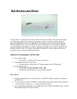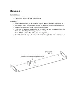
Mark the rail bracket locations and snap centerline on the rail wall
Considerations:
•
The centerline of the rail system is not typically centered on the rail wall. Please check
your final layout diagram to determine your centerline and rail bracket locations
•
The procedure below references your final drawings
Procedure:
•
Use the final elevation and layout drawing provided
•
Mark the height of each rail bracket location from the pit base to top of shaft
•
Use your measuring tape and mark the centerline as shown on the layout drawing
•
Mark centerline of rail bracket (
note: this is often offset in the shaft
) at top of rail wall
as per the plan-view drawing and with the aid of a level, snap a vertical chalk line down
the shaft from top to bottom and begin to install the brackets on the previously marked
rail bracket locations
Sliders
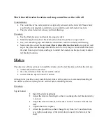
The objective of this section is to install the sliders onto the rail brackets such that the rails are:
•
centered between the brackets
•
the correct distance from the rail wall (6 inches)
•
correct distance apart (32 and 5/8 inches)
Although it is possible to only install the left sliders at this point, we recommend installing all
the sliders so that everything can be verified before installing the rails
Procedure:
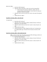
Top left slider
Install the slider hand tight
Adjust the slider left and right so that it overhangs the rail bracket arm by
½ an inch
Adjust the slider in and out so that the V notch is 6 inches from the rail
wall
Tighten the slider in place
Attach the plumb line so that it hangs freely from the V notch and runs
over right (inside) edge of the slider down to nearly the bottom of the
shaft
Summary of Contents for JOURNEY LU
Page 1: ...INSTALLATION MANUAL JOURNEY LU LA ...
Page 25: ......
Page 27: ......
Page 37: ...Adjusting the door with door tool Shim if required Installing the gibs ...
Page 39: ...Hand Rail Mounting ...


