background image

Center Distances

1.33, 1.54, 1.75, 2.06, 2.37, 2.62, 3.00, 3.25

3.75, 4.50, 5.16 and 6.00

®

Emerson Power Transmission

P O Box 687

MAYSVILLE, KY 41056

Phone: 800-626-2093

www.emerson-ept.com

F O R M

MAINTENANCE INSTRUCTIONS
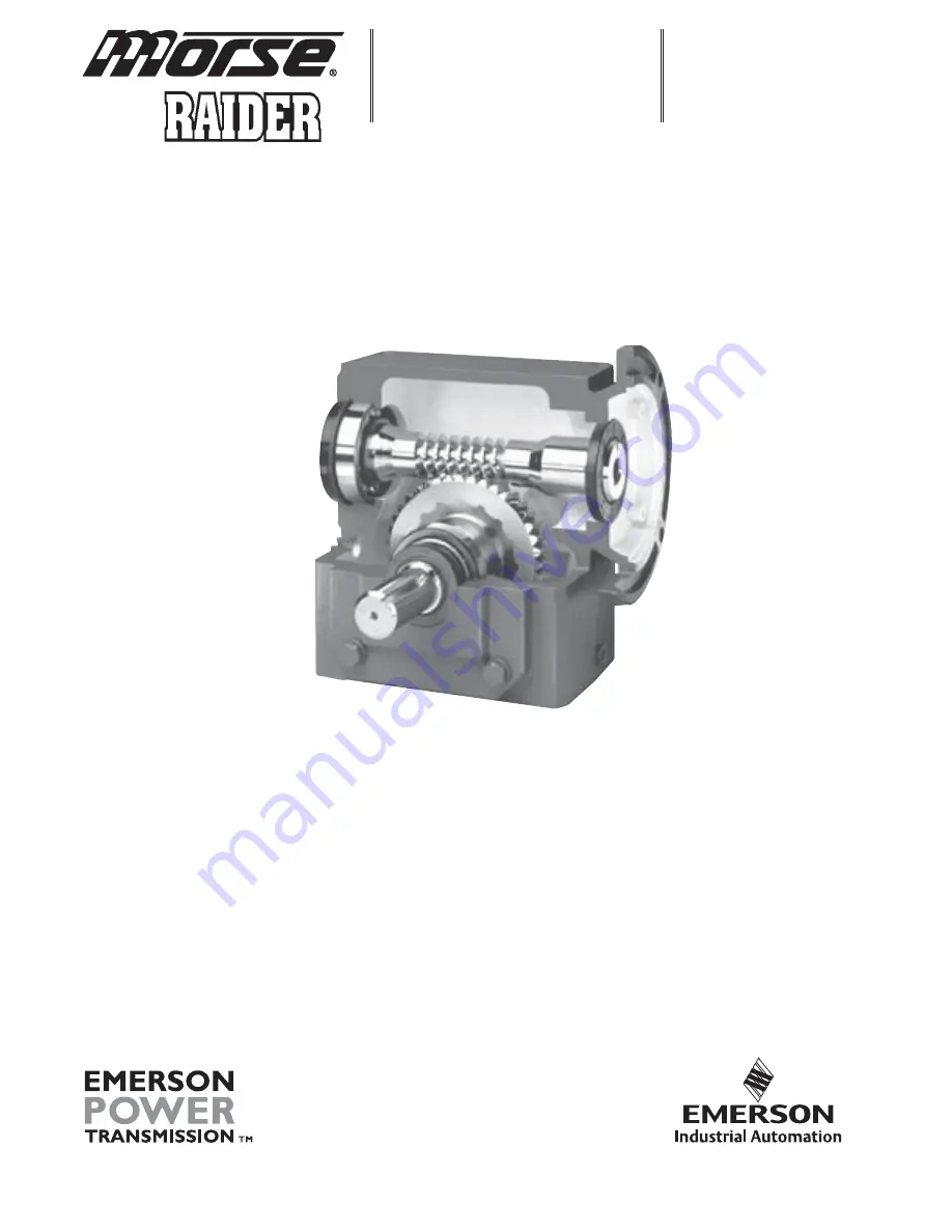
FOR WORM GEAR
SPEED REDUCERS

8721

March 2003

Summary of Contents for HVP

Page 1: ...CLEAN AIR MANAGEMENT COMPANY INC 8224 Nieman Road i Lenexa Kansas 66214 Phone 913 831 0740 Fax 913 831 9271 MODEL HVP HIGH VOLUME PULSE DUST COLLECTOR BAGHOUSE INSTRUCTION OPERATIONS MAINTENANCE MANUAL ...

Page 2: ... 1 OPERATING PRINCIPLE SECTION PARTS DETAIL 3 1 ON SITE STORAGE RECOMMENDATIONS 4 1 SETTING UP YOUR UNIT 5 1 BAG CAGE INSTALLATION 6 1 START UP CHECK LIST 7 1 START UP DUST CONTROL SYSTEMS 8 1 SHUTDOWN PROCEDURES 9 1 TROUBLE SHOOTING THE DUST COLLECTOR 10 1 TOUBLESHOOTING THE CLEANING MECHANISM 11 1 SAFETY RECOMMENDATIONS 12 1 ROUTINE MAINTENANCE 13 1 COMPONENT IOM MANUALS 14 1 ...

Page 3: ...e the appropriate repair procedure or recommend it to be returned to the factory depending on the extent of damage INSPECTION OF UNIT Housing Particular attention should be paid to the sheet metal housing of your collector The unit should be inspected for dents cracks or rips A dented housing may seriously affect the structural integrity of the unit If any of these signs are present note them on t...

Page 4: ...followed before the equipment is inspected disassembled and or serviced The equipment is automatically controlled and may start without warning unless energy supplies are properly disconnected and locked out tagged out The control panel enclosure is closed and secured except as is necessary for service or adjustment The service door is closed and secured Do not enter filter while the system exhaus...

Page 5: ... the filter media C Solids are retained on the filter media surface D Cleaning consists of a rotating pulse arm with nozzles positioned over the bags that randomly pulses 7 8 PSI air into the bags that reverses the airflow 1 This momentarily takes a row of bags off stream through pressure reversal 2 Flexing filter bags 3 Solids are released to fall towards hopper and through rotary valve or other ...

Page 6: ...ump Discharge Silencer Size Determined by Model 10 1 PD Pump Size Determined by Model 11 1 Inlet Filter Size Determined by Model 12 1 Motor TEFC 1800 RPM 208 230 460 3 60 Size Determined by Model 13 1 0 15 PSI Pressure Gauge 14 2 Drive Mount Table Support Channel 15 1 50TTA2635 x 1 Sprocket TTA35BS z 1 Torque Limiter Clutch 16 1 50A58 Drive Sprocket 17 1 Roller Chain Tensioner 18 1 206 Gearbox Dri...

Page 7: ...CLEAN AIR MANAGEMENT COMPANY INC 8224 Nieman Road i Lenexa Kansas 66214 Phone 913 831 0740 Fax 913 831 9271 3 3 ...

Page 8: ...CLEAN AIR MANAGEMENT COMPANY INC 8224 Nieman Road i Lenexa Kansas 66214 Phone 913 831 0740 Fax 913 831 9271 3 4 ...

Page 9: ...e wrapped with plastic wrap or stretch wrap to protect from moisture 3 If the bags get wet for any reason immediately lay them out with adequate ventilation to dry in order to prevent mold and mildew 4 It is recommended to store the cages inside a dry area if at all possible 5 If an inside location is not available cages can be stored outside as long as they are covered by a tarp 6 Cages are gener...

Page 10: ...ated it should be tarped to protect the finish but is not absolutely necessary VI Knife Gate 1 All limit switches solenoids and air cylinder ports must be capped and taped to prevent any moisture or dirt from entering 2 Equipment can sit outside provided it is covered with a tarp and is on a pallet or skid to keep it out of the water and dirt VII Isolation Dampers 1 All limit switches solenoids an...

Page 11: ...er ports must be capped and taped to prevent any moisture or dirt from entering 2 Unit can be stored outside provided it is covered with a tarp and is on a pallet or skid to keep it out of the water and dirt and sunlight X Level Indicators Store these items inside a cool dry area protected from rodents XI AC Inverters Store these items and all other electrical controls inside a cool dry area prote...

Page 12: ...he field may be required Rigging and Lifting Guidelines 1 Do not lift the dust collector by any attachments other than the lifting lugs provided 2 Use all of the lifting lugs provided on the dust collector or a section of the dust collector when making a lift 3 If the lifting lugs are located below the roof line of the dust collector or below the top of the section of the dust collector a vertical...

Page 13: ...re attached with a minimum of standard steel fasteners for shipment THESE MUST BE REMOVED and the PVC Bolts installed that are included in the shipment Extreme care should be exercised when installing the PVC Bolts as they are very fragile A gasket is factory installed that will provide a seal between the vent panel and the frame DO NOT use silicone sealer or any other sealer or adhesive at this j...

Page 14: ...120 volt 60 Hertz 1 Amp circuit is required to operate the dust collector s Solid State Timer A 230 460V 3 phase circuit is required to run the Pulse Arm drive motor and the Cleaning Air PD Positive Displacement pump motor Note The Adjustable Timer needs to be mounting were the Pressure Gauge on the PD Pump is visible 5 3 ...

Page 15: ... permanent mounting position Cleaning Air PD Pump The PD Pump must be install at the base of the filter to accommodate installation of the Air Supply line Securely anchor in permanent location Required line size as follows Air Supply Model Pipe Diameter HVP48 thru 112 1 HVP 152 thru 256 1 1 2 HVP 312 thru 504 2 Auxiliary Equipment All auxiliary equipment must be installed according to its manufact...

Page 16: ...ape the snap band from the opposite side of the band Then you can allow the band to expand and audibly snap into place 6 Check the fit of the snap band to the tube sheet It should be even in height above the tube sheet around the entire circumference which will confirm to the installer that the tube sheet is centered and well secured into the middle groove of the snap band 7 Lower the cage into th...

Page 17: ...e bags will have holes worn in them wherever they contact and will require replacement B High level alarms should be connected sufficiently below the air inlet s to avoid a plugged up inlet or blinded off filter bags 3 Clean air plenum A Properly install weights onto Weight Relief valve the end of the tank assembly B All bolts on the flanges must be in place and properly tighten C Verify that the ...

Page 18: ...eakage B All bolts must be properly tightened C Operate any equipment connected to the dust discharge of the dust collector Check the rotation of any motor driven equipment such as rotary airlocks horizontal unloading valves live bottom bin activators and screw conveyors Check slide gates and butterfly valves for binding 6 Explosion relief panels shear bolt style where applicable A Inspect for bro...

Page 19: ...e in the clean air plenum is not activating decrease Off time if it is bleeding air D Dust take away equipment such as rotary airlocks screw conveyors horizontal unloading valves live bottom bin activators and pneumatic conveying systems can now be started in their correct sequence E Check that all access doors hatches ports and other openings are closed and latched or bolted F The main exhaust fa...

Page 20: ...es and the differential pressure across the filter bags will also increase Slowly bring the collector to full load and note the final pressure drop across the filter bags Never allow the pressure drop across the filter bags to exceed 17 w g maximum or filter bags may collapse I Check the main airflow with a Pitot tube or equivalent measuring device to establish initial conditions If the main airfl...

Page 21: ... DOWN PROCEDURES 1 Dust control systems Reverse start up procedure shut down fan then after 5 or 10 minute delay shut down the PD pump and pulse arm drive motor 2 Pneumatic systems Reverse start up procedure shut down fan then after 5 or 10 minute delay shut down the reverse air fan and sweep arm drive motor 9 1 ...

Page 22: ... Make sure the gauge is zeroed or that the manometer is level zeroed and contains the correct fluid B Bags Loaded with Dust If the cleaning system is not operating properly refer to the section titled Troubleshooting the Cleaning System A condition known as blinding If the dust is dry see paragraph 1 4 if the dust is wet see paragraphs 5 and 6 1 Dust Not Discharging from the Hopper Check hopper fo...

Page 23: ...ir pulse to loosen caked dust If the bags were cleaned or laundered pull a bag tight around its cage you should be able to gather a small fold of material between your fingers 5 Water Leaks Inspect the dust collector housing and ductwork for holes cracks or loose gasketing where water could enter the collector 6 Condensation If moisture has been condensing inside the collector check the dew point ...

Page 24: ... that any dampers in the system are correctly positioned to allow air to flow through the dust collector D Leaks in the Housing Check the tube sheets flat steel sheets from which the filter bags are suspended and the dust collector housing for holes cracks or loose gasketing that would permit air to bypass the dust collector or filter bags III Continuous Flow of Dust in the Clean Air Exhaust Prima...

Page 25: ...Life This is often a complicated problem to diagnose and we recommend calling the factory for advice The following list may be helpful in performing some preliminary check A Temperature Operating Temperature above the recommended limit of the filter bag material B Chemical Attack Bag material degrades due to attack from certain chemicals in the dust or gasses in the air stream C High Moisture High...

Page 26: ...or ruptured valves or air bleed holes are restricted Reference attached manual Replace with a repair kit if necessary 2 Verify Positive Displacement Pump is operating correctly and producing compressed air 3 Verify weighted relief valve is weighted correctly allowing tank to build 7 8 PSI pressure B Solenoid Valve 1 Open or short circuit in wiring between timer and solenoid Check continuity with o...

Page 27: ...ng Bearing s Faulty Installation Non spec Oil Contaminated Oil Insufficient Oil Improperly Mounted Sheave Over tightened Belts Failing Gears Insufficient Backlash Non spec Oil Contaminated Oil Insufficient Oil Sever Torsional Vibration Failing Lubricated Coupling or Joint Non spec Grease Contaminated Grease Insufficient Grease Loose Attached Hardware Belt Guard Pump Mounting Bracket Frame Members ...

Page 28: ... Wrong Motor Speed Slipping Belts Excessive Rotor Clearances Abrasive Wear of Rotor Surfaces Rotor Lag Timed Leaking Oil Failed Oil Seals Foreign Material in Seal Bores Faulty Installation Non spec Oil Contaminated Oil Overheated Rotor Shafts End Cover Seams Not Tight Bolts Loose Gaskets Torn Oil Foaming Non spec Oil Oil Cavities Overfilled Chronic Fuse Blowing or Circuit Breaking Excessive Motor ...

Page 29: ...r replace one or both gear boxes as necessary 5 Pulse Arm Drive Motor rotating and sweep arm not rotating or rotating intermittently A Enter the clean air plenum and check for obstructions in the path of the rotating pulse arm Remove any obstructions B Verify that the pulse arm is rotating parallel to the tubesheet and that the nozzles do not strike the cage tops and cause the sweep arm to stop If...

Page 30: ...is locked out While servicing the filter it is very important that there are no open flames welding or grinding sparks Dust laden air could be highly explosive and extreme care must be taken Before entering any dust collector 1 Run cleaning mechanism 20 minutes with the fan off to clean filter bags 2 Discharge solids from hopper 3 Lock out electrical power on all rotating equipment 4 On toxic oper...

Page 31: ...nd screw conveyor Check seals on latter two for dust loss 4 Quarterly On Top Access Units check for dust accumulation in clean air plenum B Repairs 1 Filter bags Generally replacement although some applications can be laundered 2 Rotary Valves Usually a matter of periodic seal and blade replacement More detailed information is supplied with the valve 3 Screw Conveyors Periodic replacement of V bel...

Page 32: ...enexa Kansas 66214 Phone 913 831 0740 Fax 913 831 9271 COMPONENT IOM MANUALS MORSE RAIDER WORM GEAR SPEED REDUCER Maintenance 1 8 MARTIN TORQUE LIMITER CLUTCH 7 10 AMERICAN CONTROL PRODUCTS TIMER 11 12 DUROFLOW POSITIVE DISPLACEMENT BLOWER IOM 13 48 14 1 ...

Page 33: ...1 75 2 06 2 37 2 62 3 00 3 25 3 75 4 50 5 16 and 6 00 Emerson Power Transmission P O Box 687 MAYSVILLE KY 41056 Phone 800 626 2093 www emerson ept com F O R M MAINTENANCE INSTRUCTIONS FOR WORM GEAR SPEED REDUCERS 8721 March 2003 ...

Page 34: ... shims so this note may not apply Disconnect all before adjusting units CAUTION w e r c s p a C e z i S e u q r o T s b L t F 0 2 4 1 5 2 6 8 1 6 1 5 3 1 6 1 8 3 0 2 4 1 6 1 7 5 3 3 1 2 1 0 5 1 1 8 5 0 9 Table 1 WARNING High voltage and rotating parts may cause serious or fatal injury Turn off power to install or service Operate with guards in place Read and follow all instructions in this manual ...

Page 35: ...Push shaft assembly through housing until rear bearing outer race is free Slide bearing inner races off shaft Reverse direction and push shaft through extension end of housing and out If a press is available pressing the shaft out is preferable PARTS SERVICE 1 Housing Clean inside of housing with kerosene or solvent and then dry 2 Seal cages and end cover Remove dirt from joint faces wipe clean an...

Page 36: ...ide low speed shaft bearing onto the oiled shaft against the gear spacer F Thoroughly coat all bearings with lubrication oil 6 Worm gear and shafts A Worm and high speed shaft since all worms are integral with the high speed shaft any wear or damage to the worm will necessitate replacing both B Press shaft out of bronze worm gear To reassemble gear and low speed shaft freeze shaft or heat gear Do ...

Page 37: ...ner race onto shaft until seated against shoulder Press rear bearing outer race into housing bore opposite extension until seal cage can be installed Install seal cage Adjust end play per instructions below Item 3C 3 Low Speed Shaft Gear Shaft Assembly A Determine output shaft direction B Assemble low speed shaft assembly seal cage and end cover with shims on both seal cage and end cover Torque ca...

Page 38: ...nd as a final check B Re install reducer and accessories C Fill reducer with the recommended oil to the appropriate level See the installation instructions supplied with the reducer D Spin test for three minutes and check for noise leakage or rapid temperature rise PREVENTATIVE MAINTENANCE 1 After first week check all external capscrews and plugs for tightness 2 Periodically check oil level when g...

Page 39: ...Martin SPROCKET GEAR INC BULLETIN TL 1 TORQUE LIMITER CLUTCH DRIVE OVERLOAD PROTECTION Now in Stock at All Martin Facilities Also Stock Plate Sprockets Bored to Size and Face Ground for Torque Limiters ...

Page 40: ... vide a cushion by slipping until the torque drops to a pre set level They can be set to reduce shock loads on motors and driven equipment during reversing or inching They provide mechanical protection against breakage due to sudden overload by slipping when the pre set torque limit is reached 2 Torque Limiter Clutches Torque Limiter clutches may be used with a sprocket gear sheave flange or other...

Page 41: ... 21 18 16 14 TT70 Min Teeth MTO 48 38 33 26 21 18 16 14 Bush Lght Req d 1 4 1 4 3 8 3 8 1 2 7 8 7 8 1 Unit Min Allowable Sprocket Teeth and Length of Bushing Req d for Chain Number Size Sprocket Pitch 35 41 40 50 60 80 100 120 140 160 Min number of teeth on sprocket stocked by factory which can be used w Torque Limiter clutch Min number of teeth on made to order sprocket which will permit chain to...

Page 42: ...components manufactured and supplied by Sprocket Gear Inc in such a manner as to comply with the Williams Steiger Occupational Safety Act and with all state and local laws ordinances regulations and the American National Standard Institute Safety Code Guards access doors and covers must be securely fastened before operating any equip ment If parts are to be inspected cleaned observed or general ma...

Page 43: ...T HAND AND LEFT HAND MILD STEEL AND GALVANIZED MILD STEEL AND GALVANIZED SCREWS HOT DIPPED GALVANIZED SPECIALS SECTIONAL FLIGHTS TAIL COUPLING MILD STEEL AND DRIVE SHAFTS ELEVATOR BUCKETS HANGER STYLE 220 HANGER STYLE 226 HANGER MILD STEEL AND MILD STEEL AND STYLE 216 GALVANIZED GALVANIZED HANGER HANGER TROUGH END BEARINGS STYLE 70 STYLE 19B BALL AND ROLLER HANGER BEARINGS STYLE 220 226 HANGER BEA...

Page 44: ...EX COUPLING Stock Sintered Metal and Sinteed Steel Products HANGER BEARINGS All Steel Stock Sprockets BORED TO SIZE DOUBLE SINGLE SABER TOOTH QD HARDENED TEETH HARDEND TEETH HARDENED TEETH TRIPLE Stock Bushings Hubs BUSHINGS TYPE QD TAPERED QD IDLER STEEL WITH KEYSEAT BUSHING BUDSHING SIZE SF N Stock Gears Steel and Cast Spur Gears Stocked in both 14 1 2º 20º Pressure Angles SPUR TYPE B SPUR 3 DP ...

Page 45: ...ce Avenue 64120 P O Box 4961 Kansas City MO 64120 4961 816 231 5575 FAX 816 231 1959 Los Angeles CA 5920 S Triangle Dive Commerce CA 90040 3688 323 728 8117 FAX 323 722 7526 Minneapolis MN 10601 Hampshire Avenue South Bloomington MN 55438 2395 952 829 0623 FAX 952 944 9385 Portland OR 3030 N W Industrial Portland OR 97210 0046 503 223 7261 FAX 503 221 0203 Tampa FL 3201 Queen Palm Drive Tampa FL 3...

Page 46: ...e 20 5 Load Current Steady State 8 ma Min 1 Ampere Max 10 A Inrush 6 Voltage Drop 1 5V Typical at 1 Ampere 7 Leakage Current 5 ma 8 Dielectric Strength 1500 VRMS 9 Insulation Resistance 100 Megohms Min 10 Input Transient Protection 3000V 120V UNITS 6000V 240V units 11 Temperature Ambients Operating 40 C to 70 C Storage 55 C to 70 C 12 Humidity Operating 95 Relative 13 Linearity Option A or D 5 Min...

Page 47: ...info precisiontimer com Web Site precisiontimer com TECHNICAL BULLETIN SOLID STATE TIMING MODULE PAGE 2 OF 2 DATE 6 4 01 606 REV B CALIBRATION RESISTANCE VS TIME ACCESSORIES AVAILABLE FROM STOCK ORDER P N PM 1M 1 MEGOHM 20 PM 100K 100 KOHM 20 TYPICAL WIRING OUTLINE DRAWING MADE IN USA Order bracket mount model as 606BM T1 T2 V P1 P2 606RBM T1 T2 V P1 P2 ...

Page 48: ...PARTS LIST OPERATING AND SERVICE MANUAL D 9 610 Version 10 November 2005 Models GGB_ _B GGG_ _C_ SERIES 30 70 BLOWERS ...

Page 49: ... Quincy IL 62305 Phone 217 222 5400 Fax 217 221 8780 REMANUFACTURED BLOWERS Whenever a DuroFlow blower requires replacement or repair Gardner Denver offers an industry unique fac tory remanufactured blower exchange program From its modern Remanufacturing Center in Indianapolis IN Gardner Denver is committed to supplying you with the highest quality factory remanufactured DuroFlow blowers that are ...

Page 50: ...PD Synthetic Lubricant Description Part Number 1 Quart 28G23 Case 12Quarts 28G24 5 Gallon Pail 28G25 55 Gallon Drum 28G28 AEON PD Food Grade Synthetic Lubricant Description Part Number 1 Quart 28H97 Case 12Quarts 28H98 5 Gallon Pail 28H99 55 Gallon Drum 28H100 Call your local DuroFlow Distributor to place your order for Gardner Denver lubricants Your Authorized Gardner Denver Distributor is ...

Page 51: ...t in economical operation and minimum downtime Danger is used to indicate the presence of a hazard which will cause severe personal injury death or substantial property damage if the warning is ignored Warning is used to indicate the presence of a hazard which can cause severe personal injury death or substantial property damage if the warning is ignored Caution is used to indicate the presence of...

Page 52: ...as been relieved D Electrical shock can and may be fatal D Blower unit must be grounded in accordance with the National Electrical Code A ground jumper equal to the size of the equipment ground conductor must be used to connect the blower motor base to the unit base D Open main disconnect switch tag and lockout before working on the control D Disconnect the blower unit from its power source tag an...

Page 53: ...5 Blower Outline Dimension Chart 6 SECTION 2 INSTALLATION Location 7 Foundation and Base 7 Mounting Configurations 7 Drive Installation 7 Piping 9 SECTION 3 LUBRICATION Recommended Lubricant 10 Lubrication Instructions 10 Air Seal Vent Systems 12 Oil Sump Breathing System 12 SECTION 4 OPERATION Limitations 14 Safety Precautions 14 Blower Startup Checklist 16 SECTION 5 MAINTENANCE AND TROUBLESHOOTI...

Page 54: ...Lubricant Recommended 10 Lubricant Order Information ii LUBRICATION SECTION 3 10 Lubrication Instructions 10 Lubrication Service Air Seal Vent Systems 12 Lubrication Service Oil Sump Breathing System 12 MAINTENANCE AND TROUBLESHOOTING SECTION 5 17 Matrix Menu 1 Mounting Configurations 7 Oil Sump Breathing System 12 OPERATION SECTION 4 14 Overhaul Kits 20 Overhung Load Calculations and Limitations ...

Page 55: ...gure 2 1 Belt Drive Overhung Load Limitations 8 Figure 3 1 Approximate Oil Sump Capacities 10 Figure 3 2 AEON PD Synthetic Lubricant 10 Figure 3 3 70 Series Column Type Sight Glass Location 11 Figure 3 4 Viscosity Recommendation 13 Figure 4 1 Maximum Operating Limitations 15 EXPLODED VIEWS 30 Series Blower 200GGB810 21 70 Series Blower 201GGG810 23 ...

Page 56: ...CENTRAL TIMED COLUMN 6 DESIGN VERSION B 30 SERIES C 70 SERIES COLUMN 7 ADDITIONAL DESCRIPTION A STANDARD NO MODIFICATION COLUMNS 8 THRU 11 MODIFICATION NUMBER NOT INCLUDED IN THIS PUBLICATION CONSULT FACTORY DUROFLOW BLOWERS 30 70 SERIES MATRIX MENU NOTICE TO CUSTOMER To find the construction op tions for your blower unit FILL IN THE BALANCE OF LET TERS OR NUMBERS FROM YOUR UNIT NAMEPLATE COLUMN N...

Page 57: ...ry in Sedalia Missouri As with other precision machinery there are several relatively simple installation operation and mainte nance procedures that you must observe to assure optimum blower performance There is no guesswork in the manufacture of your highly advanced DuroFlow blower and there must be none in preparing the blower to get the job done in the field The purpose of this manual is to hel...

Page 58: ...e covers must be removed before start up Failure to remove covers from blower inlet and discharge prior to start up will cause machine damage STORAGE Your DuroFlow blower was packaged at the factorywith adequate protection to permit normal storage for up to six 6 months Under the best of storage conditions there is still a potential for damage to occur Extended storage preparation is available fro...

Page 59: ...BECOME HOR IZONTAL LEFT VERTICAL BOTTOM RO TATES LEFT TO BECOME HORIZONTAL RIGHT SHAFT ROTATION KEY CW CLOCKWISE CCW COUNTERCLOCKWISE NOTE When changing configurations be sure to relocate Oil Fill Oil Drain and Breather Filters into their proper position 30 Series blowers require a mounting foot change with a configuration change 70 Series blowers use the same mounting feet for all configurations ...

Page 60: ...D 9 610 Page 5 FIGURE 1 2 OUTLINE ...

Page 61: ...00 15 00 15 00 K 4 00 5 50 12 50 15 50 18 50 21 50 26 50 31 50 L 8 06 8 06 15 25 15 25 15 25 15 25 15 25 15 25 M 4 50 4 50 8 25 8 25 8 25 8 25 8 25 8 25 N 6 56 6 56 11 75 11 75 11 75 11 75 11 75 11 75 P 8 36 9 36 17 49 18 99 20 47 21 97 24 47 26 97 Q 2 1 2 3 6 NPT 8 FLG 8 FLG 10 FLG 12 FLG 12 FLG NPT NPT R 1 50 1 50 3 50 3 50 3 50 3 50 3 50 3 50 S 4 41 4 31 9 00 9 00 9 00 9 00 9 00 9 00 T DIA 53 5...

Page 62: ... over in the direction that places the oil sight glass es below the horizontal centerline of the blower See FIGURE 1 1 page 4 for additional configuration information When converting 30 series blowers from vertical to horizontal configurations the horizontal mounting feet are required Order horizontal mounting feet from your DuroFlow Distributor The 70 series blowers can be converted from vertical...

Page 63: ...75 0 852 1 125 0 789 1 375 0 706 0 150 0 980 0 400 0 943 0 650 0 899 0 900 0 847 1 150 0 782 1 400 0 697 0 175 0 977 0 425 0 939 0 675 0 894 0 925 0 841 1 175 0 774 1 425 0 687 0 200 0 973 0 450 0 935 0 700 0 889 0 950 0 835 1 200 0 767 0 225 0 969 0 475 0 930 0 725 0 884 0 975 0 829 1 225 0 759 2 5 Ac 125954 x HP x S F Ac D x RPM Key Ac Arc of Contact Factor Refer to Arc of Contact Factors Chart ...

Page 64: ...es DuroFlow blowers have female threaded inlet and discharge connections The connections are large enough to handle maximum volume with minimum friction loss Reducing the pipe diameter on either inlet or discharge will create unwanted restrictions that increase the overall pressure differen tial and discharge temperature of the blower The 70 Series DuroFlow blowers have flat face inlet and dischar...

Page 65: ...ins a special additive package designed for greater rust and corrosion protection AEON PD Lubricant Description Part Number 1 Quart 28G23 Case 12Quarts 28G24 5 Gallon Pail 28G25 55 Gallon Drum 28G28 AEON PD Food Grade Lubricant Description Part Number 1 Quart 28H97 Case 12Quarts 28H98 5 Gallon Pail 28H99 55 Gallon Drum 28H100 FIGURE 3 2 AEON PD SYNTHETIC LUBRICANT Machines are shipped without oil ...

Page 66: ...not overfill as this will tend to cause excessive heating of the gears and may damage the unit AEON PD Synthetic Lubricant should be drained after 6000 hours of operation Re fill with fresh AEON PD oil If mineral oil is used perform the above oil change maintenance every 1500 hours Recommended service intervals are for normal blower operating condi tions Severe operating conditions may warrant mor...

Page 67: ...8 NPT to permit installation of a venting line Do not plug these vent holes see FIGURE 1 2 page 5 Do not plug vent holes or oil sumps may pressurize causing loss of oil excessive heat and serious damage to the machine Oil Sump Breathing System All DuroFlow blowers are designed to permit their oil systems to breathe freely to prevent pressurization of the oil sumps Breather filters are required to ...

Page 68: ...ot less than 20_ F the use of oil sump heaters heated enclosures or synthetic lubricant is required For ambient temperatures 10_ F to 32_ F the use of oil sump heaters heated enclosures or synthetic lubricant is recommended The lubricant viscosity must be 70 SUS minimum at the lubricant operating temperature The pour point of the lubricant should be at least 5_ to 10_ F below the minimum expected ...

Page 69: ... HG below the maximum allowable vacuum for the blower Periodic testing of relief valves is suggested to assure that they are functioning Relief valves should be placed as close as possible to the blower inlet on vacuum systems or discharge on pressure systems Check valves must be installed on the discharge side of the blower on a pressure system and on the inlet side of the blower on a vacuum syst...

Page 70: ...50 15 15 350 7023 2600 12 16 325 7028 2600 10 16 325 DO NOT EXCEED THESE LIMITS Increased vacuum levels are attainable with water injection Contact your DuroFlow Distributor FIGURE 4 1 MAXIMUM OPERATING LIMITATIONS Blower speed line losses elevation and increased inlet temperatures affect actual blower performance Care must be taken to consider these factors when designing your system so that blow...

Page 71: ...Be sure adequate drive guards are in place to protect the operator from SEVERE PERSONAL INJURY from contact with rotating components V 9 Turn the unit over by hand to be sure there is no binding or rotor contact Special wear in seals on the 30 and 70 series are utilized in DuroFlow blowers When units are new some resistance to turning the driveshaft by hand will be encountered After several hours ...

Page 72: ...e sure to protect all interior surfaces from rusting TROUBLE SHOOTING No matter how well the equipment is designed and manufactured there may be times when servicing will be required due to normal wear the need for adjustment or various external causes Whenever equipment needs attention the operator or service technician should be able to locate the cause and cor rect the trouble quickly by follow...

Page 73: ... 19 2 Damaged seal sleeve 2 Replace sleeve See page 19 3 Gear case or drive cover 3 Clean breather filters breathers plugged 1 Endplate seal vents plugged 1 Clean vents of obstruction Do not plug seal vents 2 Worn oil seal 2 Replace seals See page 19 1 Worn oil seal 1 Replace seal See page 19 2 Damaged seal sleeve 2 Replace sleeve See page 19 1 Inadequate package design 1 Reinstall base fill with ...

Page 74: ...o your attention Factory remanufactured DuroFlow blowers are backed by a full new blower warranty 18 months from the date of shipment or 12 months in service whichever occurs first and each remanufactured blower incorporates all of the latest design technology and enhancements 3 When you install your remanufactured DuroFlow unit simply return the failed blower freight collect to ourIndianapolis IN...

Page 75: ... to Section 7 for additional part numbers as required Parts Ordering Instructions When ordering parts indicate the model and serial number from the blower nameplate and identify the blower configuration by referring to Figure 1 3 page 6 For prompt professional assistance in selecting the correct repair parts for your DuroFlow blower contact your Duroflow Distributor who maintains a large inven tor...

Page 76: ...D 9 610 Page 21 SECTION 7 PARTS LISTS AND EXPLODED VIEWS 30 SERIES DUROFLOW BLOWER EXPLODED VIEW 200GGB810 Ref Drawing ...

Page 77: ...EW 4 655EE040 655EE040 23 LOCKWASHER 4 95B5 95B5 24 PLATE VERTICAL MOUNTING 1 DF140824 200GGB247 BRACKET HORIZONTAL MOUNTING 2 DF193167 DF193167 25 CYLINDER 1 DF184565 DF184593 26 PLUG 2 64A24 64A24 27 SCREW 2 655EE04N 655EE04N 28 WASHER SPECIAL 2 DF181207 DF181207 29 SHIM SET 2 200GGB732 200GGB732 30 SLEEVE 4 DF184679 DF184679 31 ROTOR GROUP 1 203GGB4028 204GGB4028 32 KEY 1 900639910305 900639910...

Page 78: ...D 9 610 Page 23 70 SERIES DUROFLOW BLOWER EXPLODED VIEW 201GGG810 F Ref Drawing ...

Page 79: ...4AC4 64AC4 22 PLATE MOUNTING 4 DF184949 DF184949 DF184949 23 LOCKWASHER 8 95B7 95B7 95B7 24 SCREW 8 655EF080 655EF080 655EF080 25 PLUG MAGNETIC 2 64BJ3 64BJ3 64BJ3 27 PIN DOWEL 6 62M82 62M82 62M82 29 BREATHER 2 5L223 5L223 5L223 30 CYLINDER 1 DF189510 DF189511 DF189512 31 ROTOR GROUP 1 206GGG4028 207GGG4028 208GGG4028 32 KEY SQUARE 1 2800T17 2800T17 2800T17 33 HOUSING BEARING 1 300GGG006 300GGG006...

Page 80: ...AC4 64AC4 22 PLATE MOUNTING 4 DF184949 DF184949 DF184949 23 LOCKWASHER 8 95B7 95B7 95B7 24 SCREW 8 655EF080 655EF080 655EF080 25 PLUG MAGNETIC 2 64BJ3 64BJ3 64BJ3 27 PIN DOWEL 6 62M82 62M82 62M82 29 BREATHER 2 5L223 5L223 5L223 30 CYLINDER 1 DF189513 201GGG002 200GGG002 31 ROTOR GROUP 1 209GGG4028 210GGG4028 211GGG4028 32 KEY SQUARE 1 2800T17 2800T17 2800T17 33 HOUSING BEARING 1 300GGG006 300GGG00...

Page 81: ...nted Labor shall be limited to the amount specified in the Company s labor rate schedule Labor costs in excess of the Company rate schedule amounts or labor provided by unauthorized service per sonnel is not provided for by this warranty All costs of transportation of product labor or parts claimed not to be as warranted and of repaired or re placement parts to or from such service facilities shal...

Page 82: ... DuroFlow Date _______________________________________________ Your Name _______________________________________________ Your Title _______________________________________________ Your Company _______________________________________________ Address _______________________________________________ City State Zip _______________________________________________ Telephone ______________________________...

Page 83: ...A For additional information contact your local representative or Gardner Denver Compressor Division 1800 Gardner Expressway Quincy Illinois 62305 Phone 800 682 9868 Fax 217 221 8780 E mail pd blowers gardnerdenver com Visit our web site www gardnerdenver com Sales and Service in all major cities ...

Reviews: