
Page 4 of 5
CM-54
i
SURFACE MOUNT ILLUMINATED ENCLOSURE
INSTALLATION INSTRUCTIONS
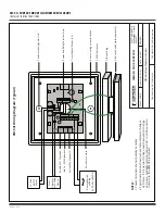
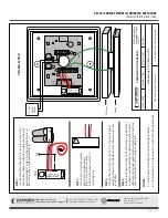
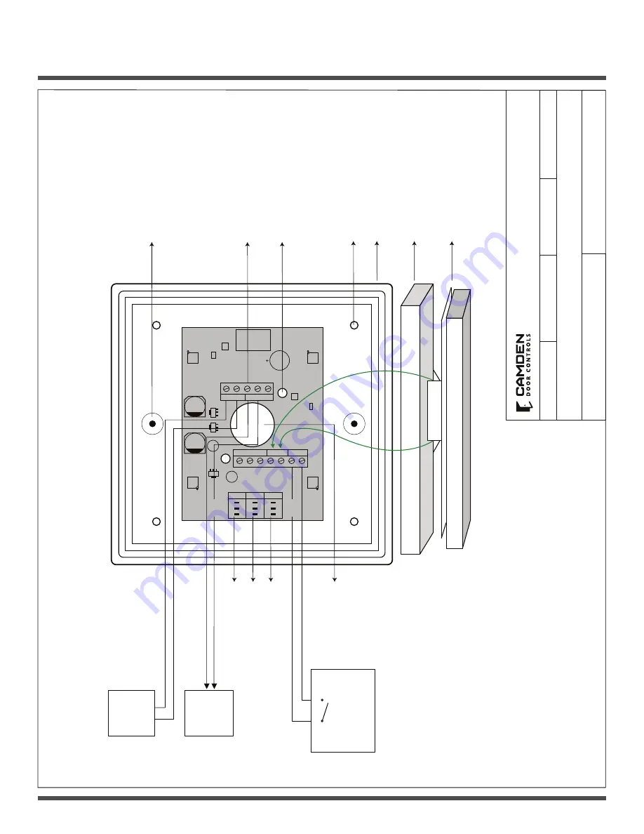
CM-54i Wiring Diagram (Typical)
CAMDEN DOOR CONTROLS
SCALE: NONE
DRAWING No: DRG-CM-54i_02
FILE NAME: CM_54i Diagram2.vsd
DRAWN BY: DGW
DATE: 04/26/17
REVISED:
5502 Timberlea Blvd. Mississauga, Ontario L4W 2T7
CM-54i Wiring Diagram (Typical)
ACTIVE
NCC
OM
NO
PWR A
C/D
C
ID
LE C
OL
ENABLE
1 2 3
O
N
D
P
1 2 3
O
N
D
P
1 2 3
O
N
D
P
-REM +
-PBTN +
ENRF/T
X -
PWR +
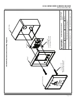
Switch mounting holes
(x
2)
All-Active Switch (sold separately)
Diffuser Ring
CM-54 Enclosure
Box mounting screw locations
Circuit Board Mount
(x
2)
Power and Relay Terminal Strip
Enable SW1 Dipswitch
Idle Col SW2 Dipswitch
Active SW3 Dipswitch
Wire Access Hole
Door
Operator or Locking
Device
Remote Switch
or Relay
(ie.
CX-33
o
r EMF-
2)
NOTE
S:
1. Power terminals are not polarity sensitive
2. Typical installation shown, where remote device changes LED color. If it is desired to have switch activation change LED color, set REMote/LOCal dip on SW1 to LOCAL and do not wire to the REMOTE terminals.
RED
GREEN
BLUE
12
/
24
V
AC/DC Power
REM/LOC
RELAY
SPEAKER


