Page 4 of 5
4
O
ff
/ O
n
1
2
3
N
.O
.
CO
M
RE
D
4
O
n
/ O
ff
1
2
3
FI
LE
N
A
M
E
:
C
M
_5
7_
G
R
D
ia
gr
am
2
.v
sd
D
RA
W
IN
G
N
o:
D
RG
-C
M
-5
7G
R
_0
2
C
M
-5
7G
R
W
iri
ng
D
ia
gr
am
(T
yp
ic
al
)
SC
AL
E:
N
O
N
E
D
RA
W
N
B
Y:
D
GW
RE
VI
SE
D
:0
4/
04
/1
3
D
AT
E:
0
7/
06
/1
2
C
am
de
n
D
oo
r
C
on
tr
o
ls
55
02
T
im
be
rle
a
Bl
vd
.
M
is
sis
sa
ug
a,
O
nt
ar
io
L4
W
2
T7
12
/ 24
V
AC
/DC
Power
Power
&
Relay
Terminal
Strip
Wire Access Hole
Circuit Board Mount
(x
2)
SW
1
Di
pswitch
SW
2
Dipswitch
Swi
tch mounting holes
(x
2)
Box mounting screw locations
(hi
dden under ci
rcuit board
) (
x4
)
CM
-57
Encl
osure
Door operator
or Locking
De
vice
All
-Active Switch
(
sold separately
)
Remote Switch
or Relay ie
- CX
-33
or EMF
-2
Optional Remote Disable Switch
Diffuser Ri
ng
N
OTES
:
1.
Powe
r terminals are not polarity sensitive
.
2.
Typical installation shown
, where remote de
vice
changes LED colour
. If i
t is de
sire
d to have
switch
activation change LED colour
, then se
t REMote
/
LOCal dip on SW
1
to LOCAL
, and do not wire to the
REMOTE terminals
.
N
.C
.
12
/
2
4
V
A
C
/
D
C
D
is
ab
le
Re
m
ot
e
Pushbutton
Re
served for
Lazerpoint TX
-9
RF Transmitter
RE
D
G
/B
G
/B
ID
LE
A
CT
IV
E
LO
C
/
RE
M
SP
EA
KE
R
RE
LA
Y
N
O
T
U
SE
D
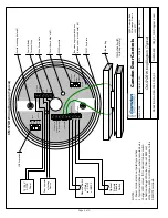
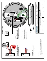
CM-57GR Wiring Diagram (Typical)


