Page 5 of 5
4
Off
/ On
1
2
3
N
.O
.
COM
RED
4
On
/ Off
1
2
3
FILENAME
:
CM
_57
GR Diagram
3.
vsd
DRAWIN
G No
: DRG
-CM
-57
GR
_03
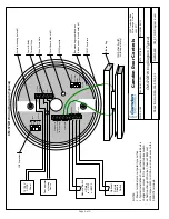
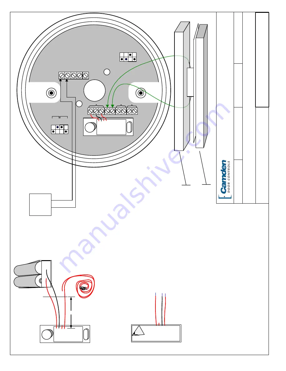
Wiring Diagram for CM
-57
GR
&
TX
-9
SCALE
:
N
ON
E
DRA
WN
BY
: DGW
REVISED
:04
/22
/13
DA
TE
:
07
/06
/12
Camden
Door Controls
5502
Timberlea Blvd
.
Missi
ssauga
, Ontario
L4
W
2T
7
12
/ 24
V
AC
/DC
Power
N
OTES
:
1.
12
/24
Powe
r terminals are not polarity sensi
tive
.
2.
This installation is intende
d for
2-
wire
re
trofit
applications
.
N
.C
.
12
/
24
V
AC
/
DC
Disable
Re
mote
RED
G
/B
G
/B
IDLE
ACTIVE
LOC
/
REM
SPEAKER
RELAY
NOT USED
TX
-9
+
-
+
-
+
-
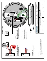
STEP
1
LAZERPOINT
CAMDEN CM-TX-9
2“
TX
-9
STEP
2
Cut the
middle
red le
ad to 1/4”
as it is not used
.
Cut both batte
ry le
ads
, and the
re
maining
switch le
ad to approximate
ly
2”
long
.
Strip the insulation back
on the
3
long e
nds to
approximate
ly 1/4”.
Turn ove
r,
and remove
re
le
ase pape
r
from double
side
d tape
.
Line
up and carefully install TX
-9
on Aura
circuit board as shown above right
STEP
3
Connect the
3
wire
s from the TX
-9
to
the
circuit board e
xactly as shown
.
The
middle re
d wire
that was cut short
is not used
.
LAZERPOINT
CAMDEN CM-TX-9
STEP
4
Install circuit board in box
, &
connect the
2
powe
r wire
s as shown
.
Se
t dipswitche
s for de
sire
d ope
ration
.
Install diffuse
r,
conne
ct push switch wi
res to
te
rminal strip
, the
n install switch
.
Te
st for prope
r operation
.
<<
Cut this lead to ¼”
Diffuser
Switch
CM-57GR & TX-9


