Page 1 of 4
CM 324 Series
Active Infrared “Hands-Free” Switch
INSTALLATION INSTRUCTIONS
Door Activation Devices
1. GENERAL DESCRIPTION
Sure-Wave™ hands-free” switch is an active infrared device
designed for use with an automatic door operator or other
access control products. Applications include low-energy doors,
drive-up windows, health-care facilities, manufacturing, etc.
The assembly fits in a variety of locations from a 1-3/4” door
frame to a 1-gang or 2-gang electrical box. Various size surface
mounting boxes are also available from Camden.
Three standard face plate widths are available:
CM-324:
2-3/4” x 4-1/2” polycarbonate or stainless steel,
fits on single gang electrical boxes.
CM-324/ N:
1-3/4” x 4-1/2” polycarbonate or stainless steel,
fits 1-3/4” door frames or our CM-23D Jamb box.
CM-324/ W:
4-1/2” x 4-1/2” polycarbonate or stainless steel, fits
on single gang, double gang or 4 x 4 electrical boxes.
All faceplates may be ordered up with a plain face (/1), with the
waving hand symbol (/2), or with the waving hand symbol and
words: WAVE TO OPEN (/3).
2. SPECIFICATIONS
Input Voltage
12-24V AC/DC ± 12%
Operating Modes
Pulse (sense) / Toggle
Operating Temp
-4 to +153 ºF (-20 to +85 ºC)
Electrical Life
100,000 Operations @ Rated Capacity
500,000 Operations @ 1/2 Rated Capacity
Current Draw
50 - 60 mA
Response Time
100 ms
Relay Output
Form 'C' (SPDT)
Output Type
Normal or Fail-Safe
Relay Contact Rating
5 amps @ 30 VDC
Time Delay
1 to 5 seconds
Connections
11" 22 AWG Leads
Security
Automatic Self-charging ID
Technology
Infra-Red with Coded Modulated Carrier
Mounting
2 x #6-32 MS
Faceplates
Jamb, 1-gang and 2-gang
Activation Range
(See Page 4)
Factory Set to 12” (304mm)
Range: 1” – 30” (25.4mm – 762mm)
Dimension
1” W x 4” L x 1-1/2” D
(25.4mm x 101.6mm x 38.1mm)
3. INSTALLATION
MOUNTING
Sure-Wave™ may be mounted in door jambs, single or double
gang electrical boxes, and 4 x 4 boxes.
NOTE: The sealing gasket (included) is recommended for
outdoor or wet locations. If using with Automatic doors
install in accordance with ANSI A156.10 / A156.19.
Select from one of the following three mounting subsections:
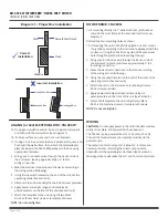
SINGLE GANG ELECTRICAL BOX: CM-324
1a. If using an in-wall box, ensure the box is plumb and square,
and flush with the wall surface (See Diagram 1).
1b. If using a surface box, ensure it is secure and plumb.
2. Bring your 4-conductor wire through the back or side of the
enclosure and leave approximately 6” tail for wiring connection.
3. Make the electrical connections to the device according to
the wiring section (following).
4. Using the dip switch located on the end of the unit, set the
operating mode (See Section 4) .
5. Attach the unit to the enclosure using the two #6-32
screws provided.
6. Apply power and adjust range and time delay via the
potentiometers on the front of the unit
(See Section 4 for adjustments).
7. Attach the faceplate to the unit using the two black
#6-32 x 3/8 machine screws or tamper-proof screws.
NOTE: Do not overtighten


