Page 8 of 33
CV-550 SPK V3 REFERENCE MANUAL
INSTALLATION INSTRUCTIONS
Power Supply
12 to 24 VDC
+12V
ALARM
NC
NO
COM
D0
D1
D_IN
OPEN
GND
RED
GREY
ORANGE
BLUE
PURPLE
Green
White
BROWN
YELLOW
BLACK
Blue
Green
Alarm Annunciator
Connect positive wire to
colored wire
representing the
preferred color of the
dome light.
Camden Model: CM‐AF142SO
(+ve)
Push to Exit Switch
Camden Model:CM‐30
Black
(‐ve)
Red
(+ve)
(+ve)
+
‐
Normally Open
Camden Model: CV‐550SPK v
3
120 VAC
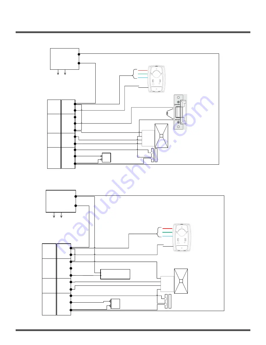
Wiring the CV‐550SPK
V3
to an external card reader and door strike
Door Position Switch
5‐16 VDC
Ground
Data 0
Data 1
External Wiegand Card Reader
Normally Closed
Door Strike 12 VDC
(+)
(‐)
(Can be replaced with a MOV)
Camden Model:
CX‐ED1079
D1
Camden Model: CV‐7400
Stand Alone Keypad
Must be configured for single door mode
Power Supply
12 to 24 VDC
+12V
ALARM
NC
NO
COM
D0
D1
D_IN
OPEN
GND
RED
GREY
ORANGE
BLUE
PURPLE
Green
White
BROWN
YELLOW
BLACK
Blue
Green
Alarm Annunciator
Connect positive
wire to colored
wire
representing the
preferred color
of the dome
light.
Camden Model: CM‐AF142SO
(+ve)
Push to Exit Switch
Camden Model:CM‐30
Black
(‐ve)
Red
(+ve)
(+ve)
+
‐
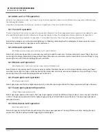
Maglock
Normally Open
Camden Model: CV‐550SPK v
3
120 VAC
Wiring the CV‐550SPK
V3
to an external card reader and maglock
Door Position Switch
Camden Model: CX‐90/91 Series
5‐16 VDC
Data 0
Data 1
Ground
Wiegand Card Reader
Normally Closed
Camden Model:CV‐7400


