Page 16 of 28
12
- 24V
AC/DC Power
12
- 24V
Power for
Strike
Fail-secure Electric Strike
Shown
If Fail-Safe lock is used, wire to Terminals 1 & 2)
N/O
M
ai
nt
ai
ne
d
D
ry
C
on
ta
ct
Only
LE
D
1
C
X-33
LE
D
2
LE
D
3
D
IS
P
LA
Y
R
el
ay
1
R
el
ay
2
R
el
ay
3
N/C
N/C
N/O
N/O
N/O
N/C
CO
M
CO
M
CO
M
PO
WER
12/24V
AC/DC
DR
Y 1
DR
Y 2
DR
Y 3
DR
Y 4
+ W
ET
IN
PU
T
IN
PU
T
IN
PU
T
IN
PU
T
-IN
PU
T
M
EN
U
U
P
D
O
W
N
0.0.
5
N
O
TE
S:
D
oo
r
O
pe
ra
to
r
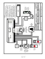
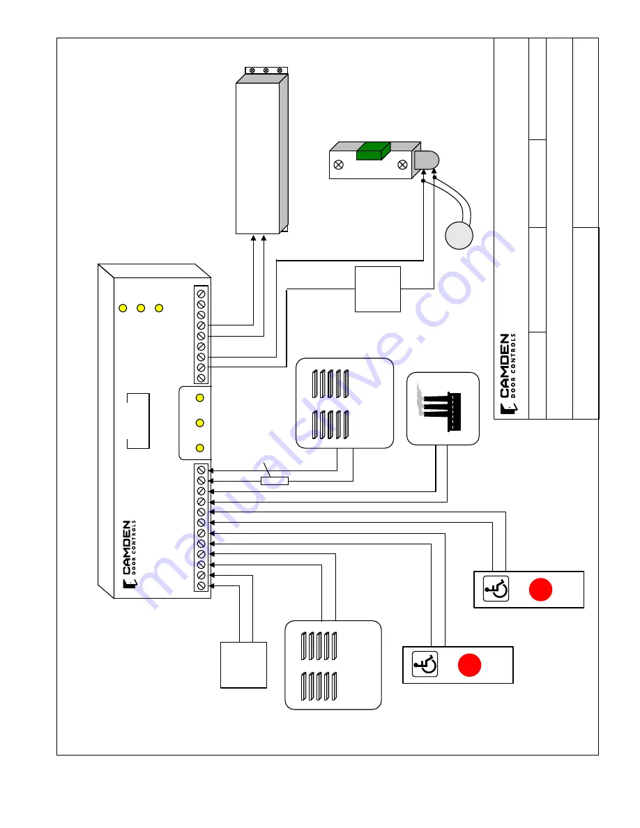
1. All inputs are momentary. 2. Enterphone signal may be wet (powered) or
dry contact closure. (both are shown below)
3.
Ve
st
ib
ul
e
sw
itc
h
is
o
nl
y³ ‘
ac
tiv
e’
w
he
n
th
e
st
rik
e
is
e
ne
rg
iz
ed.
4.
In
si
de
s
wi
tc
h
al
w
ay
s
un
lo
ck
s
an
d
op
en
s
do
or
5.
Fi
re
A
la
rm
In
pu
t #
4
fir
es
re
la
y #’s 2 & 3,
an
d
ho
ld
s
bo
th
u
nt
il i
np
ut
is
re
le
as
ed.
6.
R
el
ay
#3
ca
n
be
u
se
d
fo
r a
s
ta
tu
s
in
di
ca
to
r.
7. Wet I/P activates on 4.5V AC/DC. Older
interphone panels may produce a stray
voltage when inactive causing a false Wet I/P
activation. In these cases please use the
provided 50Ω
, 1W resistor in series with the
Wet Input,isolation relay or if available Dry 1
Input.
Apartment
Interphone Panel
(Dry contact)
Unlocks
door only
Apartment
Interphone Panel (Powered signal)
Unlocks
door only
Ve
st
ib
ul
e
(or courtesy)
Switch
In
si
de
Switch
FIRE
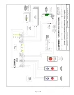
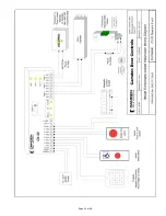
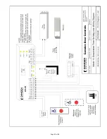
(Mode 5) Apartment/Condo Application Wiring Diagram
CAMDEN DOOR CONTROLS
SCALE: NONE
DRAWING No: DRG-CX-33-05
FILE NAME: CX-33 Diagram 5 rev2.vsd
DRAWN BY: DGW
DATE: 07/05/13
REVISED: 04/28/15
5502 Timberlea Blvd. Mississauga, Ontario L4W 2T7
M
O
V
Optional 50Ω, 1W resistor for stray voltages.
Summary of Contents for CX-33
Page 10: ...Page 10 of 28...
Page 11: ...Page 11 of 28...
Page 12: ...Page 12 of 28...
Page 13: ...Page 13 of 28...
Page 14: ...Page 14 of 28...
Page 18: ...Page 18 of 28...
Page 19: ...Page 19 of 28...
Page 20: ...Page 20 of 28...
Page 21: ...Page 21 of 28...
Page 22: ...Page 22 of 28...
Page 23: ...Page 23 of 28...


