Page 25 of 28
M
EN
U
U
P
D
O
W
N
M
O
V
P
U
S
H
N
.C
.
�
A
LA
R
M
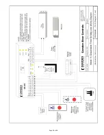
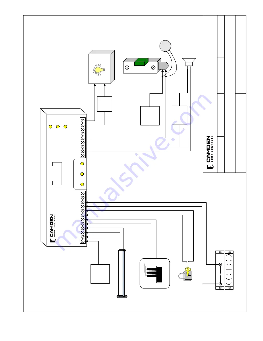
(Mode 14) Delayed Relay Activation Application Wiring Diagram
CAMDEN DOOR CONTROLS
SCALE: NONE
DRAWING No: DRG-CX-33-14
FILE NAME: CX-33 Diagram 14 rev.vsd
DRAWN BY: DGW
DATE: 05/05/15
REVISED:
5502 Timberlea Blvd. Mississauga, Ontario L4W 2T7
LE
D
1
C
X-33
LE
D
2
LE
D
3
R
el
ay
1
R
el
ay
2
R
el
ay
3
N/C
N/C
N/O
N/O
N/O
N/C
CO
M
CO
M
CO
M
PO
WER
12/24V
AC/DC
DR
Y 1
DR
Y 2
DR
Y 3
DR
Y 4
+ W
ET
IN
PU
T
IN
PU
T
IN
PU
T
IN
PU
T
-IN
PU
T
D
IS
P
LA
Y
0.0.
14
N
O
TE
S:
1.
Th
is
p
ro
du
ct
d
oe
s
no
t c
ar
ry
a
ny
U
L
Ap
pr
ov
al
o
r
ce
rti
fic
at
io
n
fo
r t
hi
s
m
od
e.
2.
Ti
m
er
(H1)
se
ts
th
e
le
ng
th
o
f t
im
e
th
e
Pu
sh
/
Pa
ni
c
sw
itc
h
m
us
t b
e
pr
es
se
d &
he
ld
b
ef
or
e
th
e
do
or
u
nl
oc
ks
3.
Ti
m
er
(H2)
se
ts
th
e
m
in
im
um
O
N
ti
m
e
fo
r t
he
e
le
ct
ric
lo
ck
a
fte
r r
el
ea
se
o
f t
he
P
us
h /
Pa
ni
c
sw
itc
h
4.
Th
e
By
pa
ss
o
r S
hu
nt
s
w
itc
h
In
pu
t a
nd
th
e
Fi
re
P
an
el
In
pu
t e
ss
en
tia
lly
d
o
th
e
sa
m
e
thing –
ac
tiv
at
e
re
la
y #’s 2 & 3.
12
- 24V
AC/DC Power
Fire Panel
Input
(N/O dry contact)
Shunt/Bypass
Switch
(maintained)
Magnetic Contact Switch
Normally closed contact
when door is closed
Push & Hold Switch until Door Unlocks
FIRE
12
- 24V
Power for
Strike
Power if req’d
Power for Siren
Electric Lock
Local Siren
or Horn
Alarm or Bypass
Light
Not for use as UL compliant delayed egress.
Summary of Contents for CX-33
Page 10: ...Page 10 of 28...
Page 11: ...Page 11 of 28...
Page 12: ...Page 12 of 28...
Page 13: ...Page 13 of 28...
Page 14: ...Page 14 of 28...
Page 18: ...Page 18 of 28...
Page 19: ...Page 19 of 28...
Page 20: ...Page 20 of 28...
Page 21: ...Page 21 of 28...
Page 22: ...Page 22 of 28...
Page 23: ...Page 23 of 28...


