Page 26 of 28
FI
LE
N
A
M
E: CX-33 Lock down mode.vsd
D
R
A
W
IN
G
N
o: DRG-CX-33-7a
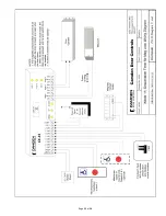
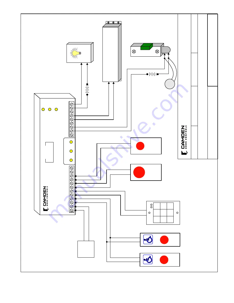
(Mode 7)
´L
oc
k-down
´ Mode Wiring Diagram
SC
AL
E: NONE
DRAWN BY: DGW
R
EV
IS
ED:
D
AT
E: 07/07/16
C
am
de
n
D
oo
r
C
on
tr
o
ls
55
02
Timberlea Blvd
Mississauga, Ontario L4W 2T7
M
O
V
LED 1
CX-33
LED 2
LED 3
Relay 1
Relay 2
Relay 3
N/C
N/O
COM
N/C
N/O
COM
N/C
N/O
COM
POWER
12/24
V
AC/DC
DRY 1
DRY 2
DRY 3
DRY 4
+ WET
INPUT
INPUT
INPUT
INPUT
- INPUT
MENU
UP
DOWN
1
2
3
4
5
6
7
8
9
�
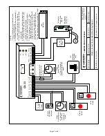
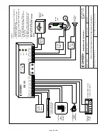
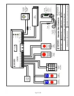
Lock-Down
PUSH TO
LOCK DOWN
PUSH
TO
RESET
´Lock-Down´
Indicator
(Can be part of
Lock-Down
Switch)
Fail-Safe
Electric Strike
Shown
Wire MOV
(Supplied)
directly to strike or
magnet
12-24 V AC/DC Power
Outside
Wall Switch
Inside
Wall Switch
Optional Secure
Entry/Reset
Power for Strike
Reset Switch
(In office)
Lock-Down
Switch (In office)
(If Fail-Secure lock is used,
wire to
Terminals 1 & 2)
Power for LED
Door
Operator
DISPLAY
0.0.
7
Summary of Contents for CX-33
Page 10: ...Page 10 of 28...
Page 11: ...Page 11 of 28...
Page 12: ...Page 12 of 28...
Page 13: ...Page 13 of 28...
Page 14: ...Page 14 of 28...
Page 18: ...Page 18 of 28...
Page 19: ...Page 19 of 28...
Page 20: ...Page 20 of 28...
Page 21: ...Page 21 of 28...
Page 22: ...Page 22 of 28...
Page 23: ...Page 23 of 28...


