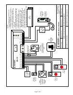
Page 6 of 28
CX-33 Advanced Logic Relay Installation Instructions
provided on the relay outputs – they are dry contacts).
Once input and output connections are made, program the
unit according to the General Programming Instructions on
page 1, and walk-test the installation. Timing adjustments
may need to be made.
It is NOT recommended to add the “Delay-on-activate”
(or nuisance delay) feature in this mode!
Once the desired operation is achieved, proceed to Section 4,
Pg 9 for
System Inspection Instructions
.
Section 3H
Normally Locked Restroom
(Mode 8)
In this mode, control of a normally locked single occupant
barrier-free washroom is obtained. It allows the user to secure
the door from the inside by depressing a Push-to-Lock button.
The exterior means of ingress is removed electronically from
the circuit.
To exit the washroom, simply exit manually via the store-room
function lever-handle set (the Door Contact Switch resets the
relay), or, press the interior wall switch to unlock and signal
the door operator. Exiting the washroom resets the relay, and
the door is re-locked upon closure.
The CX-33 also provides a relay dedicated for “Occupied &
“Door Locked” signage (recommended).
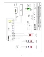
Refer to
Diagram 8
, (Page 19) for the following connections.
The outside means of ingress – Keypad, Key switch, or
Prox-reader, plus the inside wall switch, and Push-to-Lock
switch are all N.O. momentary devices. Connect as shown.
The Door Contact circuit must be closed when the door is
closed and open when the door opens.
A fail-secure electric strike is typically used, although a
fail-safe strike can also be used. Connect to Relay 1. The
automatic door operator connects to Relay 2, and the signage
connects to Relay 3. (As a reminder, no power is provided on
the relay outputs – they are dry contacts).
As a safety feature, the door cannot be “secured” via the
“Push-to-Lock” button until the door is completely closed (to
prevent kids from pressing the lock button and running away).
Once input and output connections are made, program the
unit according to the General Programming Instructions on
page 1, and walk-test the installation. Timing adjustments
may need to be made.
It is NOT recommended to add the “Delay-on-activate”
(or nuisance delay) feature in this mode!
Once the desired operation is achieved, proceed to Section 4,
Pg 9 for
System Inspection Instructions
.
Section 3J
Lock-out Relay Plus
(Mode 9)
This mode combines, for the first time, a lintel mount safety
sensor lock-out relay (LOR) with a switching network (aka
make/break relay). The voltage sensing circuit can be utilized
with motors/controls up to 120 volts AC/DC. The adjustable
hold timer (lock-out) is then matched to the door closing
time. “Cancellation” inputs are provided for connection to
rail-mounted door beams.
In addition, three inputs and two relays are provided for the
switching network function.
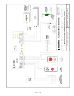
Refer to
Diagram 9
, (Page 20) for the following connections.
LOR Circuit:
A parallel connection is made to the two motor wires running
from the Operator (motor) to its control. If the motor is AC,
then polarity is not an issue. The CX-33 is triggered by the
AC voltage going from high to low.
If the motor is DC, then the wires are polarity sensitive. If
Relay 3 LED doesn’t illuminate when the door is closing, then
just reverse the two terminal connections at the CX-33.
Input 1 is for the N.O. relay contacts of the photo beam.
The beams are typically mounted at the end of guide rails
and designed to reset the LOR in the event anyone should
walk into the swing path when the door is in the closing cycle.
Relay 3 output is to be connected in SERIES with the safety
device and the Safety Circuit of the operator.
Optional Switching Network:
Wire the activating device(s) to DRY 1, DRY 2 or DRY 3
terminals. Wire the outputs as shown to Relays 1 & 2.
Once input and output connections are made, program the
unit according to the General Programming Instructions on
page 1, and walk-test the installation. Timing adjustments
may need to be made.
It is NOT recommended to add the “Delay-on-activate”
(or nuisance delay) feature in this mode!
Once the desired operation is achieved, proceed to Section
4, Pg 9 for
System Inspection Instructions
.
Summary of Contents for CX-33
Page 10: ...Page 10 of 28...
Page 11: ...Page 11 of 28...
Page 12: ...Page 12 of 28...
Page 13: ...Page 13 of 28...
Page 14: ...Page 14 of 28...
Page 18: ...Page 18 of 28...
Page 19: ...Page 19 of 28...
Page 20: ...Page 20 of 28...
Page 21: ...Page 21 of 28...
Page 22: ...Page 22 of 28...
Page 23: ...Page 23 of 28...


