Page 21 of 26
CX-33PS Advanced L
ogic Cont
rol Relay & P
ower Supply C
abinet
IN
ST
ALLA
TION
IN
STR
UC
TION
S
FILENAME:
CX
-33PS Diagram 11.ai
D
R
AWING
No:
DRG-CX-33-PS-11
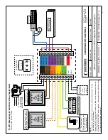
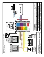
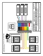
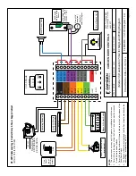
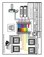
(Mode 11) Deactivation Timer for Mag Lock
W
iring Diagram
S
C
A
LE
:
N
O
N
E
D
R
AWN
BY:
JML
R
E
V
ISE
D:
DATE: 04/17/2020
55
02
T
im
be
rle
a
B
lv
d.
M
iss
is
sa
ug
a, O
ntar
io
L4
W
2
T7
CAM
DEN
D
O
O
R
CO
NT
RO
LS
NOTES:
1.
The magnetic contact Switch circuit must be closed when the door is closed,
and open when the door opens. 2.
When the N/O Fire
Alarm Circuit closes, the Mag Lock is released, and the wall
switch inputs are disabled. 3.
Sensor is only active after Switch is pressed, and remains active until door closes.
4.
All items in dashed lines are optional.
MOV
Magnetic Contact Switch
N.C.
AC
AC
DRY 1
IN
PUT
DRY 2
IN
PUT
DRY 3
IN
PUT
DRY 4
IN
PUT
+
W
ET
-
IN
PU
T
RELAY 1 COM
RELAY 1 N
O
RELAY 1 N
C
RELAY 2 COM
RELAY 2 N
O
RELAY 2 N
C
RELAY 3 COM
RELAY 3 N
O
RELAY 3 N
C
*
+
VD
C
-
VD
C
DISPL
AY
MENU
UP
DOWN
0.
1
.
1
CX
-33
M
ode
12
0
VA
C
Tr
an
sf
or
m
er
CX-
TR
X-5024
24
VA
C,
50 VA
PUSH
TO OPEN
PUSH
TO OPEN
Mag Lock
FIRE
Wire Momentary
Switch(es) to Input 1
Maintained Signal on Input 2 holds Outputs 2 & 3 (optional)
Po
w
er
ed Signal
ie. RF Receiver
(same
ope
ration
as Dry 1)
Fire
Alarm Input.
N/O dry contact unlocks
door and disables normal operation
Door #1 Operator


