CX-ED1259-L ‘RIM’ Electric Strike
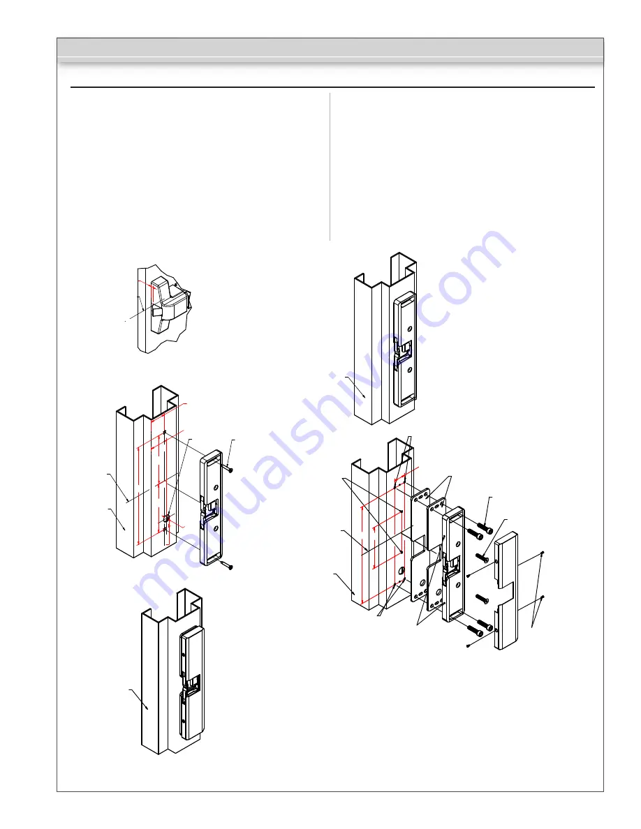
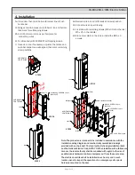
1a. Close door, then mark horizontal center line of Push
bar keeper.
2a. Using center line, measure (101.5mm) top and bottom,
then mark for self-tapping screws.
2b. Drill (15mm dia.) Hole, as per template, for
connecting wires
2c. Fix strike body with SCW425T self-tapping screws.
3. Close door, and if necessary, adjust so that strike and
push bar keeper are well aligned, then mark remaining
screw positions.
4a. Remove strike, and drill threads at screws position.
4b. Connect wires as per drawing.
4c. Fix strike with remaining screws (M6 x 30 at both ends /
M5 x 25 in the middle)
4d. Place cover plate on the strike. Install the M2.5 x 4
screws.
4. Installation
Page 2 of 3
R
HORIZONTAL
CENTERLINE
HORIZONTAL
CENTERLINE
Jamb
Self-tapping SCREWS x 2pcs
(SCW425T)
Wire hole
106,5
106,5
213
21,5
R+23
R+28
n 15
Jamb
Jamb
M6(2pcs)
Jamb
HORIZONTAL
CENTERLINE
M5(2pcs)
M6(2pcs)
M6 x 30 SCREW x 4pcs
(SC630A)
M5 x 25 SCREW x 2pcs
(SC525E)
Spacer (Install as needed)
M2.5 x 4 SCREW x 4pcs
M2.5(4pcs)
213 90
25
STEP 1
STEP 3
STEP 2
STEP 4
STEP 5
Note: The products are intended to be installed in accordance with the
installation wiring diagram and mechanically assembled drawings
provided with each product. The local authority having jurisdiction (AHJ)
and the National Electric Code, NFPA 70. When installed with a fail secure
manner, the local authority shall be consulted with regard to the use of
possible panic hardware to allow emergency exit from the secure area.
The electric door strike shall be installed in such a way and in such
location as not to impair the operation of an emergency exit or panic
hardware mounted on the door.


