Call: 1.877.226.3369 / 905.366.3377
Visit: www.camdencontrols.com
Opening New Doors to
Innovation, Quality and Support!
Page 7 of 7
File: CX-EPD-1289L Manual.indd
Rev.: July 21, 2022
Part No.: 40-82B249
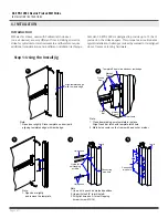
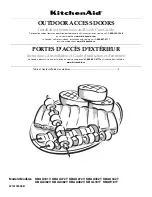
Cover plate
flush with
frame
7
CX-EPD-1289L Electric Preload RIM Strike
INSTALLATION INSTRUCTIONS
Other Considerations
Although the considerations above will address the majority of installation steps needed for
a successful installation, there are a few additional items that you will need to check for:
Summary
Adherence with the recommendations of this guide will avoid the most common problems
associated with the installation of RIM strikes. If you require additional assistance, please
contact our Technical Support department by phone at 1-877-226-2269 or email
support@camdencontrols.com.
•
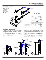
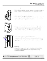
Consideration for deadlocking latch (as shown here).
If exit device has a deadlocking latch, the CX-EPD-1289L RIM strike must be mounted so that
the deadlocking latch does not enter the latch cavity of the RIM strike. Position the strike so
that the deadlocking latch rests against the face of the strike.
•
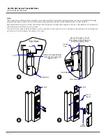
Consideration of the free movement of the exit device latch and the keeper (jaws) of the
RIM strike.
Ensure the exit device latch and the keeper (jaws) of the electric strike have free and easy
movement to operate together, with minimum friction. In this, a small amount of silicone
lubricate on both the latch and jaws of the strike will improve operation. Do not over spray.
•
Consideration for a professionally finished retrofit installation.
Replacing electric strikes used with cylindrical or mortise locksets, with an exit device and RIM
strike, will leave holes in the door and door frame that must be filled or covered. Cover or plug
holes and check that new cover plates are flush with the frame and will not interfere with
the RIM strike.


