CONNECTIONS
OPERATIONS
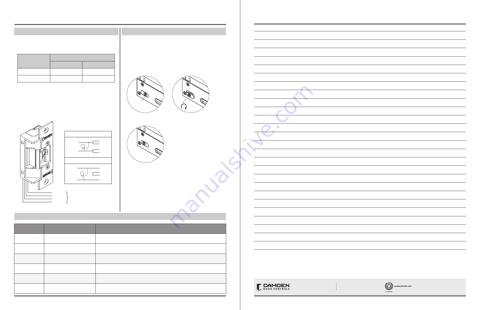
A Varistor is provided to protect strikes from large volume spike. Connect
varistor between the two input wires. Connection of the varistor varies
based on input voltage. Please refer following table for more details;
Power
Varistor Connection
+ve end
-ve end
12V
Red/Black
Blue/Green
24V
Red
Green
Note:
• For UL 294 and UL 1034 compliance, the door strikes are to be
powered via a UL 294 or UL 603 class 2 power limited output from
a control panel and/or power supply. In addition, when powered
by AC or DC, the units must have a UL-regulated UL 294 or UL 603
power limited class 2 output rated at 12 or 24 volts, as well as an AC
on indicator.
Red
Black
Blue
Green
Black
Red
Blue
Green
Black
Red
Blue
Green
(+12V)
( - )
(+24V)
( - )
12V
24V
Varistor
Varistor
Power
Power
POWER
12VDC
Red/Black: +12V
Blue/Green: Ground
A varistor is provided to protect strike from spikes.
Connect varistor between input wires.
Fail Safe
Changing
Fail Secure
24VDC
Red:
+24V
Black/Blue:
-
Green:
Ground
How to modify fail-safe to fail-secure or vice versa.
1. Loosen the screw as per the product diagram below.
2. Rotate the set plate 180
°
and slide the plate until
it is properly seated.
3. Tighten the screw.
Note: For UL 294 / UL 1034 compliance the door strikes are to be
powered via a UL 294/ UL 603 class 2 power limited output from a
control panel and or power supply. Furthermore, when powered
by AC/DC, the units shall use a UL regulated UL 294/UL 603 power
limited class 2 output rated 12/24V with AC on indicator.
Red
Black
Blue
Green
Black
Red
Blue
Green
Black
Red
Blue
Green
(+12V)
( - )
(+24V)
( - )
12V
24V
Varistor
Varistor
Power
Power
POWER
12VDC
Red/Black: +12V
Blue/Green: Ground
A varistor is provided to protect strike from spikes.
Connect varistor between input wires.
Fail Safe
Changing
Fail Secure
24VDC
Red:
+24V
Black/Blue:
-
Green:
Ground
How to modify fail-safe to fail-secure or vice versa.
1. Loosen the screw as per the product diagram below.
2. Rotate the set plate 180
°
and slide the plate until
it is properly seated.
3. Tighten the screw.
Note: For UL 294 / UL 1034 compliance the door strikes are to be
powered via a UL 294/ UL 603 class 2 power limited output from a
control panel and or power supply. Furthermore, when powered
by AC/DC, the units shall use a UL regulated UL 294/UL 603 power
limited class 2 output rated 12/24V with AC on indicator.
How to change from fail-safe to fail-secure and vice versa
• Loosen the screw as per the product diagram below.
• Rotate the set plate 180° and slide the plate until it is properly
seated.
• Tighten the screw.
ORDERING INFORMATION FOR PART REPLACEMENT
ITEM
PART NUMBER
DESCRIPTION
1
60-31A083
Commutateur de capteur sans contact avec contrôle LED externe
2
60-40E036
Advanced Logic Control Relay And 2 Amp Power Supply In Pre-Wired Metal Cabinet
3
CX-MDA
Magnetic Door Contact
4
CX-ED2079
Grade 2 Universal Electric Strike
5
CM-7536/4
36’’ Column “Push To Open” Switch
6
CM-7536/8B
36’’ Column ‘’Push To Lock’’ Switch
CX-WC17VR-PS SERIES RESTROOM KIT
INSTALLATION INSTRUCTIONS
CX-WC17VR-PS SERIES RESTROOM KIT
INSTALLATION INSTRUCTIONS
Notes :
1.
2.
3.
4.
5.
6.
7.
8.
9.
10.
11.
12.
13.
14.
15.
16.
17.
18.
19.
20.
21.
22.
23.
24.
25.
26.
Questions? Call us toll-free at 1-877-226-3369 or technical support 905-366-3377 (ext. 505)
Call: 1.877.226.3369 / 905.366.3377
Visit: www.camdencontrols.com
Opening New Doors to
Innovation, Quality and Support!
File: WC17VR-PS.indd
Rev.: December 7th 2022
Part No: 40-82B271VR
Page 5 of 9
Page 6 of 9
Figure 4.3 Connection for CX-ED2079
Figure 4.4 Fail Safe and Fail Secure mechanism for CX-ED2079


