background image

Page 9 of 18

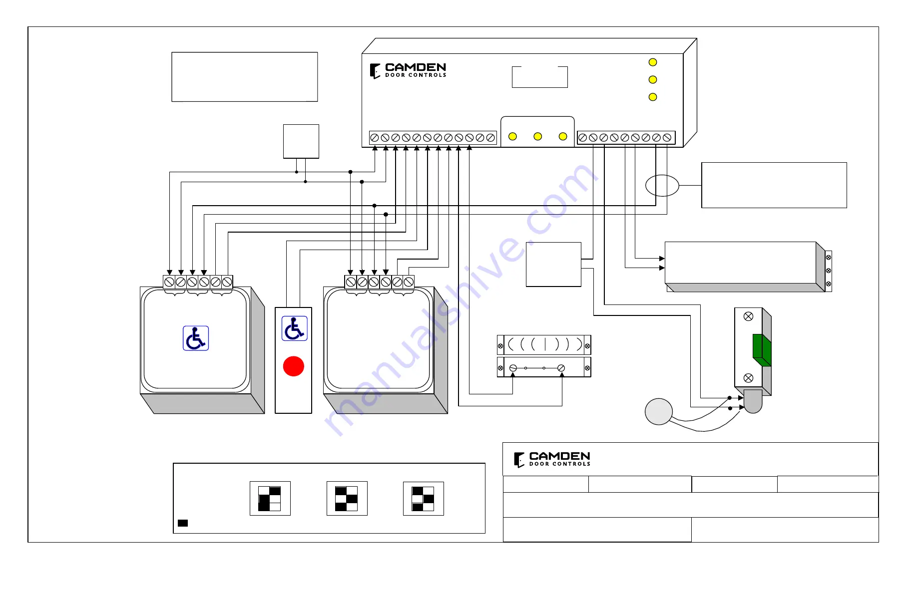
WC13 SERIES RESTROOM CONTROL

INSTALLATION INSTRUCTIONS

Inside

Wall Switch

(always unlocks

& opens door)

FILENAME :

WC-13-7 wiring diagram_R2

DRAWING No: DRG-CX - WC-13-7

WC-13 Washroom Package 

Wiring Diagram 

(

normally unlocked) 

SCALE:  NONE

DRAWN BY:  DGW

REV:  2

DATE :  03/07/17

Magnetic

Contact

Switch

Fail-Safe Electric

Strike Shown

Outside Wall Switch

CM-45/455SE1 (or similar)

Inside ‘Push-to-Lock’

CM-45/855SE1 (or similar)

MOV

Wire MOV (supplied)

directly to strike 

(If Fail-Secure lock is used,

wire to Terminals 1 & 2)

N.C.

Contacts closed

when Door

is closed 

12 / 24 VDC

 Power

For Strike

12

/24

Po

w

er

R

em

ote

N.

O. 

Re

la

O

ut

put

LED 1

LED 2

LED 3

DISPLAY

Relay 1

Relay 2

Relay 3

N

/C

N

/O

CO

M

N

/C

N

/O

CO

M

N

/C

N

/O

CO

M

POW

ER

12

/24

V

AC

/DC

D

RY

 1

D

RY

 2

D

RY

 3

D

RY

 4

W

ET

IN

PU

T

IN

PU

T

IN

PU

T

IN

PU

T

- I

N

PU

T

MENU

UP

DOWN

0.0.

7

Door Operator

12

/24

Po

w

er

R

em

ote

N.

O. 

Re

la

O

ut

put

Important:

Ensure wiring polarity is consistent

from Relay 3 to each Aura Remote

Input terminals

+

-

Part# 40-82D003 

CAMDEN DOOR CONTROLS

5502 Timberlea Blvd.

Mississauga, Ontario

L4W 2T7


12 - 24 V

AC/DC

Power

PUSH

TO

OPEN

PUSH

TO OPEN

PUSH

TO

LOCK

CX-33

Note:

This Drawing should be used in addition 

to each products respective Installation 

Manual (not in place of).

Aura

Dip Switch

Settings

1

REM/LOC

RELAY

SPEAKER

2

3

Enable

ON

1

RED

GREEN

BLUE

RED

GREEN

BLUE

2

3

Active Color

ON

1

2

3

Idle Color

ON

= Switch Position

Summary of Contents for WC13 Series

Page 1: ...bove their posted values Always measure voltages provided on both the VDC VAC scales sources first before applying power to any part of the Restroom Control Kit Wiring of this unit is dependent on the...

Page 2: ...p Down LED 1 LED 2 LED 3 Power 12 24 AC DC Dry 1 Input Dry 2 wet Input Input Dry 3 Input Dry 4 Input Com N C Com N O N C Com N O N C N O Relay 1 Relay 2 Relay 3 Display Multi function Relay REM PBTN E...

Page 3: ...454SE1 CM 45 854SE1 CM 45 4 SWITCHES a Use the 6 32 hex head screws to tighten the aura insert slightly b Fit in the assembled CM 45 4 by locating the screws with the holes on the backplate c Fit the...

Page 4: ...Door Contact 60 42C019 Mounting Box Flush Aura Enclosure Flame Impact Resistant Black Polymer ABS 6 1 2 W X 6 1 2 H X 2 D 60 42C010 Mounting Box Surface Aura Enclosure Flame Impact Resistant Black Po...

Page 5: ...12 24V Power Remote N O Relay Output LED 1 LED 2 LED 3 DISPLAY Relay 1 Relay 2 Relay 3 N C N O COM N C N O COM N C N O COM POWER 12 24V AC DC DRY 1 DRY 2 DRY 3 DRY 4 WET INPUT INPUT INPUT INPUT INPUT...

Page 6: ...12 24V Power Remote N O Relay Output Part 40 82D003 CAMDEN DOOR CONTROLS 5502 Timberlea Blvd Mississauga Ontario L4W 2T7 12 24 V AC DC Power Important Ensure wiring polarity is consistent from Relay...

Page 7: ...vd Mississauga Ontario L4W 2T7 PUSH TO OPEN PUSH TO LOCK Push To Open Inside Push To Open always unlocks opens door Push to Lock combination Switch WC13AXFM SM Washroom Package Wiring Diagram normally...

Page 8: ...PUSH TO LOCK Push To Open Inside Push To Open always unlocks opens door Push to Lock combination Switch WC13AXFM SM Washroom Package Wiring Diagram normally locked CX WC13AXFM 8 CX WC13AXFM 8 AI May 1...

Page 9: ...LOCK Push To Open Inside Push To Open always unlocks opens door Push to Lock combination Switch 12 24 V AC DC Power Note This Drawing should be used in addition to each products respective Installatio...

Page 10: ...LOCK Push To Open Inside Push To Open always unlocks opens door Push to Lock combination Switch 12 24 V AC DC Power Note This Drawing should be used in addition to each products respective Installatio...

Page 11: ...or similar CM 450R 12 CM AF501SO CM AF141SO 24 VDC Power Supply GRY BLK N O N C BLK MOV GRY 12 24 V AC DC Power Note This Drawing should be used in addition to each products respective Installation M...

Page 12: ...wer Supply GRY BLK N O N C BLK MOV GRY 3 4 12 24 V AC DC Power Note This Drawing should be used in addition to each products respective Installation Manual not in place of Note To unlock the door in t...

Page 13: ...ns door Push to Lock combination Switch 12 24 V AC DC Power 12 24 Power Remote N O Relay Output Push To Open Note This Drawing should be used in addition to each products respective Installation Manua...

Page 14: ...ens door Push to Lock combination Switch 12 24 V AC DC Power Fail Secure Electric Strike Shown If Fail Safe lock is used wire to Terminals NC COM Wire MOV supplied directly to strike Note This Drawing...

Reviews: