2
4
5
6
7
PERLA VC
AGATA VC
OPALE
KT V
KT V
KT V
KT V
PERLA VC
AGATA VC
OPALE
EN
INSTALLATION
INSTRUCTIONS
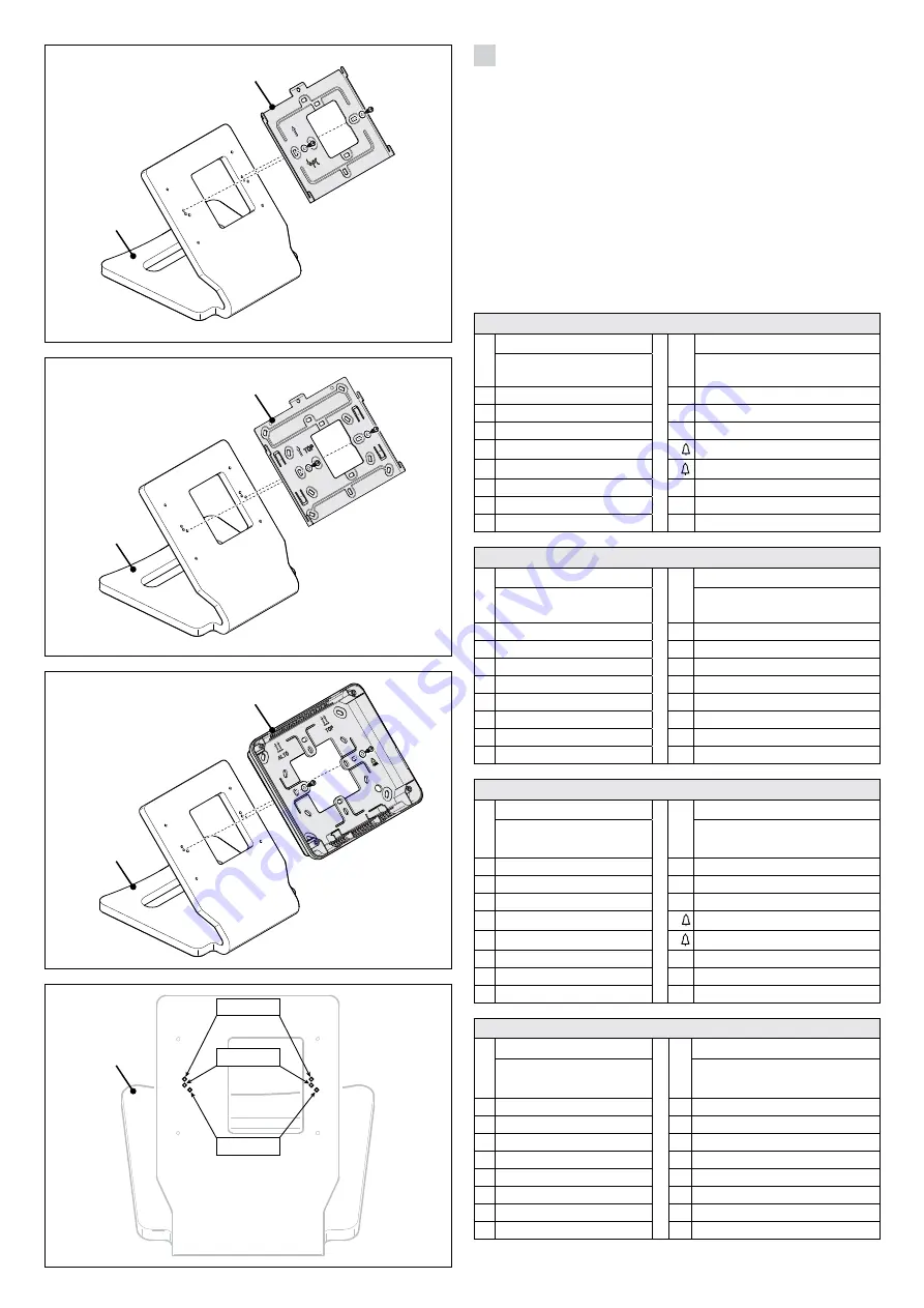
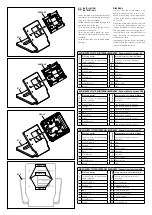
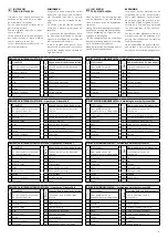
Fasten the base or mounting bracket of
the receiver to the table-top mounting,
using the screws provided.
Thread the cable provided through the
dedicated hole at the rear.
Carry out the cabling following the in-
structions in the tables.
Close the rear cable gland slot by at-
taching the metal plate with the screws
provided.
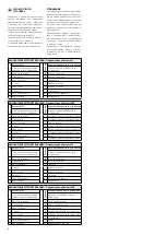
Fix the sticky tabs into the dedicated
housings.
DISPOSAL
Do not litter the environment with
packing material: make sure it is dis-
posed of according to the regulations
in force in the country where the prod-
uct is used.
When the equipment reaches the end
of its life cycle, take measures to ensure
it is not discarded in the environment.
The equipment must be disposed of
in compliance with the regulations in
force, recycling its component parts
wherever possible.
Components that qualify as recyclable
waste feature the relevant symbol and
the material’s abbreviation.
AUDIO ENTRY SYSTEM INTERNAL RECEIVERS - Connections to System X1
Pin no
.
RJ45 connector
Ter
minal
Internal receiver terminal block
Colour of wires in connecting
cable supplied
Function of internal receiver's
terminals
1 White-Orange
B
Line
2 Orange
B
Line
3 White-Green
Free
4 Blue
+
Doorbell
5 White-Blue
–
Doorbell
6 Green
Free
7 White-Brown
AL
Alarm Input
8 Brown
Free
AUDIO ENTRY SYSTEM INTERNAL RECEIVERS - Connections to System 200
Pin no
.
RJ45 connector
Ter
minal
Internal receiver terminal block
Colour of wires in connecting
cable supplied
Function of internal receiver's
terminals
1 White-Orange
Free for additional functions
2 Orange
Free for additional functions
3 White-Green
5
Common (ground)
4 Blue
8
Audio to receiver
5 White-Blue
9
Audio from receiver
6 Green
Free for additional functions
7 White-Brown
7
Call
8 Brown
Free for additional functions
VIDEO ENTRY SYSTEM INTERNAL RECEIVERS - Connections to System X1
Pin no
.
RJ45 connector
Ter
minal
Internal receiver terminal block
Colour of wires in connecting
cable supplied
Function of internal receiver's
terminals
1 White-Orange
B
Line
2 Orange
B
Line
3 White-Green
+
Power supply
4 Blue
+
Doorbell
5 White-Blue
–
Doorbell
6 Green
–
Power supply
7 White-Brown
AL
Alarm Input
8 Brown
Free
VIDEO ENTRY SYSTEM INTERNAL RECEIVERS - Connections to System 200
Pin no
.
RJ45 connector
Ter
minal
Internal receiver terminal block
Colour of wires in connecting
cable supplied
Function of internal receiver's
terminals
1 White-Orange
3
Positive video
2 Orange
4
Negative video
3 White-Green
5
Common (ground)
4 Blue
8
Audio to receiver
5 White-Blue
9
Audio from receiver
6 Green
6
+Power supply
7 White-Brown
7
Call
8 Brown
20
Doorbell input


