+
-
A
B GND
EbA EbA EbI EbI
S2
S1
2
EM
4
3
L1T
L2T
+
E
-
L1T
L2T
24V
0V
EbA
EbA
EbI
EbI
Pa
g
e
1313
-
M
an
u
al c
od
e:
11
9
G
3
13
6
11
9
G
3
13
6
ve
r.
2
0
3
/2
0
14
© C
A
M
E c
an
ce
lli auto
m
ati
ci s.p.a. - T
h
e d
ata a
n
d i
n
fo
rm
ati
on p
rovi
d
ed i
n th
is m
an
u
al a
re s
u
b
je
ct to c
h
an
g
e at a
ny ti
m
e w
ith
ou
t p
ri
or n
oti
ce by C
A
M
E C
an
ce
lli A
u
to
m
ati
ci S
.p.a.
ENGLISH
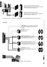
Devices already connected
Entrance/exit sensor
Transformer
Electric lock
White
Brown
Green
Blue
Blue
Red
Red
Red
Red
White
Black (120 V AC)
White
Red (230 V AC)
Device configuration:
• The direction arrows with display
①
automatically detect the direction of the transit. DIP 1 and 2 only serve to display (ON) or not (OFF)
the two arrows individually.
• The direction arrows
②
, however, must be tested by relaying a command and checking that the green light switches on in the direction
of transit. Otherwise, invert the positions of DIP switches 1 and 2, as one must be ON and the other OFF (DIP both OFF = steady green
arrows, DIP both ON = steady red arrows).
• The courtesy light
③
must be jumpered.
②
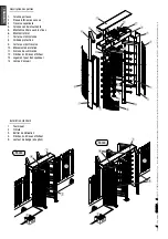
Direction arrows
①
Direction arrows
with display
③
LED courtesy light
Devices to be connected

