3 mm
Pa
g
e
1717
-
M
an
u
al c
od
e:
11
9
G
3
13
6
11
9
G
3
13
6
ve
r.
2
0
3
/2
0
14
© C
A
M
E c
an
ce
lli auto
m
ati
ci s.p.a. - T
h
e d
ata a
n
d i
n
fo
rm
ati
on p
rovi
d
ed i
n th
is m
an
u
al a
re s
u
b
je
ct to c
h
an
g
e at a
ny ti
m
e w
ith
ou
t p
ri
or n
oti
ce by C
A
M
E C
an
ce
lli A
u
to
m
ati
ci S
.p.a.
ENGLISH
Function
Description
F-15
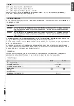
Independent entrance/exit control.
This function is only active in "independent" mode (see F-11) and disables F-8 and
F-14.
Select the entrance/exit control mode according to the following table:
selection
Controlled
Controlled
Unrestricted
Restricted
Restricted
Unrestricted
Controlled
Restricted
Restricted
Controlled
Controlled
Unrestricted
Unrestricted
Controlled
Key
Controlled = access allowed only to authorised users
= green and flashing
Unrestricted = unrestricted entrance
= green arrow
Restricted = entrance denied for all users
= red arrow
F-16
Write data in
Saves registered users and data settings in
.
F-17
Read data from
Loads registered users and data settings from
.
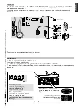
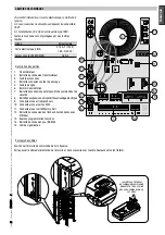
Adjusting the hydraulic damper
Proper adjustment of the hydraulic damper is a necessary condition for the correct turnstile operation with reduction of mechanical
stress on the system. Both the working temperature and duty cycle must be taken into account to properly adjust the hydraulic damper.
Remove line voltage during installation and make sure that the tripod moves freely.
Turn the central column rotating until the springs are at their maximum extension;
temporarily lock the column.
Loosen the nut
Turn the damper until the distance from the block is 3mm ; tighten the nut .
Loosen the ring nut locking screw ; turn the adjustment
ring nut clockwise until the turnstile begins to
slowdown when turning the column.
Turn the power ON.
Perform simulated use and, while slowly turning
the ring nut clockwise or anti-clockwise, adjust
the braking force of the rotating mechanism: it
must smoothly reach the end run when slowing
down.
Make sure that slowdown is as expected for each position
of rotation.
Fully tighten the ring nut locking screw
nut.
FINAL OPERATIONS


