
P
ag.
31
- Manuale
FA01610-IT
- 08/2021 - © C
AME S.p.A. - I contenuti del manuale sono da ritenersi suscettibili di modifica in qualsiasi momento senza obb
ligo di pr
eav
viso. - Istruzioni originali
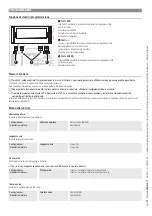
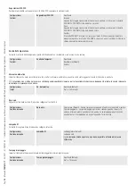
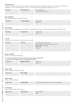
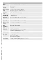
Cambia password
Permette di cambiare la password di 4 cifre che protegge l'accesso al menu principale.
Password
Cambia password
Utilizzare le frecce ed il pulsante Enter per comporre il codice desiderato.
Menu F
Abilita la vista del menu funzioni F.
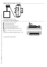
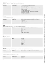
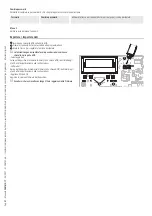
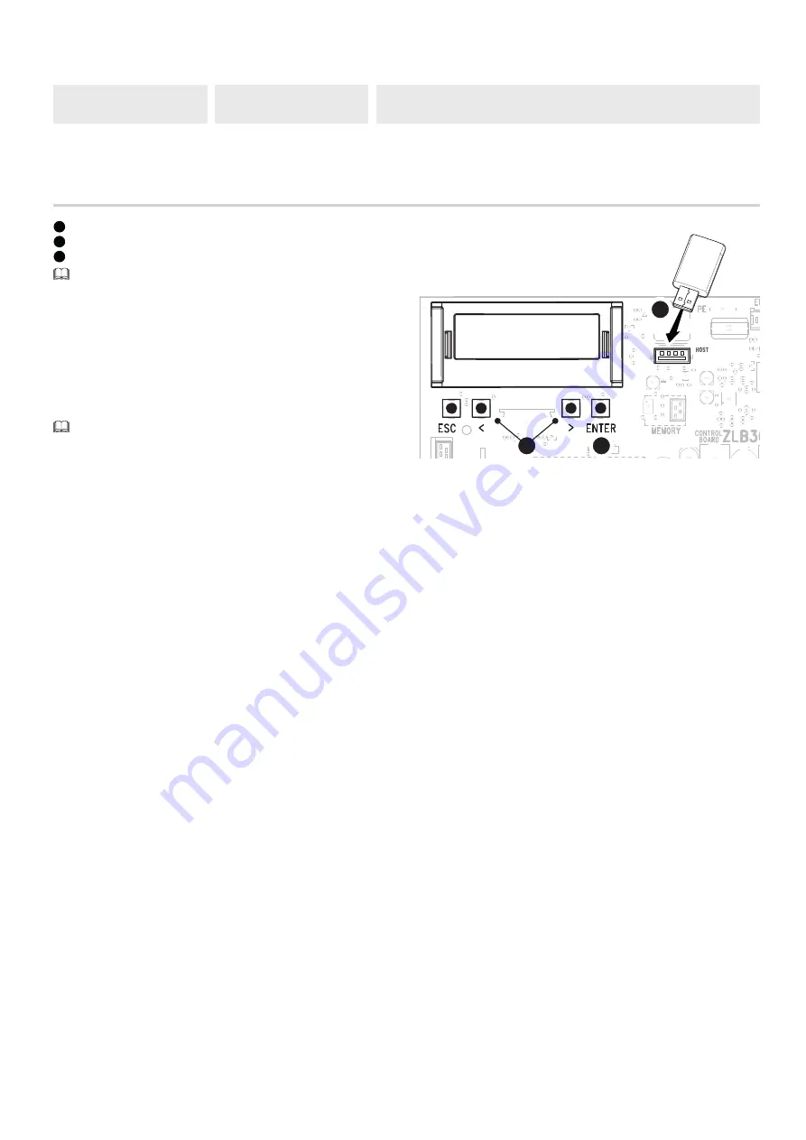
Esportare / importare dati
1
Inserire una chiavetta USB nella porta USB.
2
Premere il pulsante Enter per accedere alla programmazione.
3
Usare le frecce per scegliere la funzione desiderata.
Le funzioni vengono visualizzate solo quando viene inserita una
chiavetta nella porta USB.
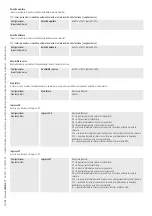
-Salvataggio dati
Salva nel dispositivo di memoria (memory roll o chiave USB) i dati relativi agli
utenti, alle temporizzazioni e alle configurazioni.
-Lettura dati
Carica dal dispositivo di memoria (memory roll o chiave USB) i dati relativi agli
utenti, alle temporizzazioni e alle configurazioni.
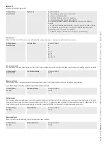
-Aggiorna FW da USB
Aggiorna la versione firmware del dispositivo.
Accertarsi che la chiavetta contenga il file di aggiornamento firmware.
2
3
1
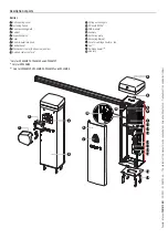
Summary of Contents for 803BB-0120
Page 121: ...GARD PX Brushless GPX40MGP GPX40MGS GPX40MGC GPX40MXP GPX40MCP FA01610 RU RU...
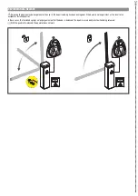
Page 122: ...1 2 2 1...
Page 123: ...3 FA01610 RU 08 2021 CAME S p A 2006 42 CE 2006 42 CE 2006 42 CE III 20 1 5 3 2006 42 CE...
Page 124: ...4 FA01610 RU 08 2021 CAME S p A CAME S p A UNI EN ISO 14001...
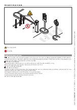
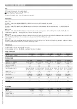
Page 129: ...9 FA01610 RU 08 2021 CAME S p A 20 2 6 5 2 0 0 220 145 4 0 0 7 0 0 500 24...
Page 130: ...10 FA01610 RU 08 2021 CAME S p A 1500 1 2 3 4...
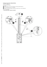
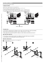
Page 131: ...11 FA01610 RU 08 2021 CAME S p A 1 2 3 90 4 5 6 7 90 8 DX SX 1 2 3 4 5 6 7 8...
Page 132: ...12 FA01610 RU 08 2021 CAME S p A 4 UNI6954 4 8x13...
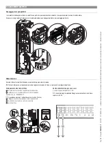
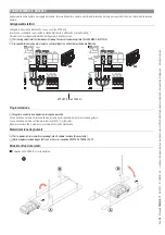
Page 134: ...14 FA01610 RU 08 2021 CAME S p A 1 2 3 4 5 6 3 2 1 4 5 6...
Page 135: ...15 FA01610 RU 08 2021 CAME S p A 1 2 45 3 4 45 4 1 2 3...
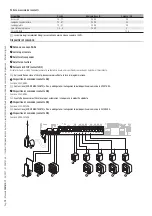
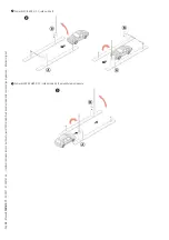
Page 136: ...16 FA01610 RU 08 2021 CAME S p A 89 1 2 3 GPX40MCP GPX40MGP GPX40MXP _ 2 1 1 3...
Page 137: ...17 FA01610 RU 08 2021 CAME S p A 1 2 3 GPX40MCP GPX40MGP GPX40MXP _ 1 89 1 1 2 3...
Page 142: ...22 FA01610 RU 08 2021 CAME S p A 3 2 1 1 ESC ESC 2 3 ENTER ENTER ESC 3 4...
Page 148: ...28 FA01610 RU 08 2021 CAME S p A 1 250 ENTER CLr TW TW...
Page 149: ...29 FA01610 RU 08 2021 CAME S p A 1 1 250 2 ENTER 3 ENTER 4 5 ENTER GUI 3 3 10 5 1 1000 1 1000...
Page 152: ...32 FA01610 RU 08 2021 CAME S p A 1 USB USB 2 Enter 3 USB USB USB USB 2 3 1...
Page 153: ...33 FA01610 RU 08 2021 CAME S p A 4 3 2 1...
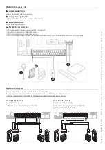
Page 156: ...36 FA01610 RU 08 2021 CAME S p A 2 2 3 B 3 2 7 A B...
Page 158: ...38 FA01610 RU 08 2021 CAME S p A RSE CAME TWIN ARM...
Page 159: ...39 FA01610 RU 08 2021 CAME S p A...


