background image

STYLO: 

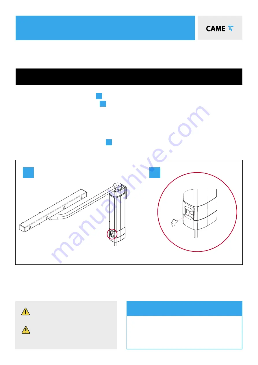
MANUAL RELEASE

To manually RELEASE THE NON-REVERSIBLE GEARMOTOR:

1.  Slide open the hatch covering the lock 

A

2.  Insert key into lock and turn until it clicks 

B

3.  With your other hand firmly open the gate. The gate should be manually released. Now fully open the gate carefully at 

the same speed as the automatic operator.

4.  To re-engage, close the gate and turn the key back to its original position. Attempt to manually move the gate to 

ensure it is fully engaged.

5.  To re-engage, close the gate and return the release lever back to its original position, pushed completely back into 

place. Take the key out and replace the cap 

B

. Attempt to manually move the gate to ensure it is fully engaged.

Basic Maintenance: Hints & Tips

•  Slide back manual release cover & spray locking 

mechanism with suitable penetrating lubricant.

•  Lubricate gate hinges.
•  Manually release the gates at least once per month.

The STYLO straight arm swing gate operator has a release mechanism located behind the 

hatch at the bottom of the unit.

ALWAYS isolate the power supply as 

instructed by your installer (even in a 

power cut).

Release any additional locking 

device fitted to the gate (eg. electric 

lock etc).


a

B

Summary of Contents for 8K01MB-0576 STYLO KIT

Page 1: ...for a single swing gate weighing up to 100kg per leaf max width 1 8m QUICK SETUP GUIDE Typical gate setup geometry Gate motor manual release Kit wiring diagram Control panel guide safety TO BE READ I...

Page 2: ...ode Transmitter STYLO ME Motor x2 8K01MB 0576 KIT CONTENTS AF43S Radio Frequency Card 1 Kit Contents 2 Safety Instructions 3 Typical Gate Setup 4 Geometry 5 Manual Release Instructions 6 Kit Wiring Di...

Page 3: ...ssing through the gate Keep feet away from the bottom of the gate during operation Do not operate the gate by remote control unless it is in view Do not attempt to block or interfere with the gate mov...

Page 4: ...cells are used in pairs one transmitter and one receiver They should be installed between 500 600mm from the ground facing each other Power for the photocells is taken from the control panel 24v AC Th...

Page 5: ...the slower the opening speed and the greater the gear motor s thrust Opening A mm C mm D mm 90 90 0 200 400 90 230 180 300 135 230 0 300 D A C OUTward OPENING gates For outward opening gate geometry...

Page 6: ...the gate and return the release lever back to its original position pushed completely back into place Take the key out and replace the cap B Attempt to manually move the gate to ensure it is fully en...

Page 7: ...7 ZL92Z Control Panel 10 2 TX C NC TX 2 RX TX DIR Photocells Cable length RX 4 Core 0 5mm Flex TX 4 Core 0 5mm Flex 1m 30m Mains Supply 230 V AC Cable length 1m 20m 3 Core 1 5mm 20m 30m 3 Core 2 5mm...

Page 8: ...motor cables for motor 2 Connections M2 N2 Leave the gate in the halfway position 9 Setup the Encoder A 3 1 10 The Gate will now perform a close and open cycle 12 Exit the programming using the button...

Page 9: ...l now appear on the screen Press and release a button on a transmitter the number on the screen will increment by one for each button pressed A maximum of 25 individual buttons can be saved Remove tra...

Page 10: ...activation from a command device to restart C1 REOPENING DURING CLOSING When the automation is in its closing cycle and the safety circuit is triggered the automation will stop and reverse its motion...

Page 11: ...blue backlighting RAL7024 Grey colour 806SL 0310 SELR2BDG Flush mounted Bus transponder reader for cards keyfobs and TAG Manchester protocol with blue backlighting RAL7024 Grey colour 001R700 Programm...

Page 12: ...House Maxted Road Maylands Ind Est Hemel Hempstead Herts HP2 7DX Tel 01442 230 800 CAME BPT Ireland Unit 9 The Westway Centre Ballymount Dublin 12 Tel 353 0 1 450 7442 8K01MB 0576 QS0922 2022 EN YOU...

Reviews: