background image

P

age 

13

 - Manuel 

FA01165 -FR

 - 05/2018 - © CAME S.p.A. - T

raduction des instructions originales

ENTRETIEN

Entretien périodique


Avant toute autre opération d'entretien, il est conseillé de mettre hors tension pour éviter toute situation de danger provoquée par des 

déplacements accidentels du dispositif.

Registre d'entretien périodique tenu par l'utilisateur (semestriel)

Date

Remarques Signature

Summary of Contents for AX3024

Page 1: ...AX3024 AX5024 IT Italiano IT Italiano EN English FR Français RU Русский FA01165M04 Automazione per cancelli a battente MANUALE DI INSTALLAZIONE ...

Page 2: ... LE AREE DI MANOVRA DEL CANCELLO CONTROLLARE CHE NON VI SIA VEGETAZIONE NEL RAGGIO D AZIONE DELLE FOTOCELLULE E CHE NON VI SIANO OSTACOLI SUL RAGGIO D AZIONE DELL AUTOMAZIONE NON PERMETTERE AI BAMBINI DI GIOCARE CON I DISPOSITIVI DI COMANDO FISSI O DI SOSTARE NELL AREA DI MANOVRA DEL CANCELLO TENETE FUORI DALLA LORO PORTATA I DISPOSITIVI DI COMANDO A DISTANZA TRASMETTITORI O QUALSIASI ALTRO DISPOS...

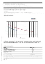
Page 3: ... parti da leggere con attenzione Questo simbolo indica parti riguardanti la sicurezza Questo simbolo indica cosa comunicare all utente LEGENDA Destinazione d uso Dati tecnici Tipo AX3024 AX5024 Grado di protezione IP 44 Alimentazione V 50 60 Hz 230 AC Alimentazione motore V 24 DC Assorbimento max A 10 Potenza W 120 Spinta N 500 4500 Tempo di apertura a 90 s REGOLABILE Intermittenza Lavoro SERVIZIO...

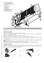
Page 4: ...ro 3 Staffa cancello 4 Vite M8x35 UNI5737 per fissaggio staffa pilastro 5 Boccola 6 Dado M8 UNI5588 per fissaggio staffa pilastro 7 Passaguaina 8 Fermo meccanico 9 Viti M6x20 UNI5739 per fermo meccanico 10 Perno della vite senza fine 11 Rondella Ø8x24 UNI6593 12 Vite fissaggio staffa cancello al perno M8x10 UNI5739 13 Staffa di fissaggio 14 Sportellino di sblocco Descrizione delle parti Pag 4 Manu...

Page 5: ... in chiusura verificare che il punto di fissaggio del motoriduttore sia in una zona protetta da urti e che la superficie di fissaggio sia solida prevedere nella rete di alimentazione e conformemente alle regole di installazione un adeguato dispositivo di disconnesione onnipolare che consente la disconnessione completa nelle condizioni della categoria di sovratensione III ovvero con una distanza ma...

Page 6: ...il dimensionamento a tabella deve essere riconsiderato sulla base degli assorbimenti e delle distanze effettivi Per i collegamenti di prodotti non contemplati in questo manuale fa fede la documentazione allegata ai prodotti stessi INSTALLAZIONE Le seguenti illustrazioni sono solo esempi in quanto lo spazio per il fissaggio del motoriduttore e degli accessori varia a seconda degli ingombri Spetta a...

Page 7: ...Maggiore è l angolo di apertura dell anta maggiore è la velocità di apertura e minore la spinta del motoriduttore Minore è l angolo di apertura dell anta minore è la velocità di apertura e maggiore è la spinta del motoriduttore Assemblare e saldare le due parti della staffa pilastro Fissare la staffa sul punto prestabilito con tasselli e viti adeguate o se il pilastro è metallico saldarla Pag 7 Ma...

Page 8: ...lo Fissare lo snodo alla staffa pilastro con la vite e il dado Su ante non metalliche assemblare e saldare le due parti della staffa e fissarle con viti adeguate Saldare la staffa cancello sull anta rispettando le quote riportate in tabella Nota per i motoriduttori AX5024 è necessario inserire un ulteriore spessore di 10 mm tra il cancello e la staffa Coda a snodo Boccola Coda a snodo Boccola Vite...

Page 9: ...a UNI6593 Ø8 Sbloccare il motoriduttore vedi paragrafo sblocco manuale portare l anta in posizione di massima apertura allentare i dadi del fermo meccanico di apertura posizionarlo in battuta con il perno attacco e fissarlo Fermo meccanico apertura Perno attacco Portare l anta in posizione di chiusura allentare i dadi del fermo meccanico di chiusura posizionarlo in battuta con il perno attacco e fis...

Page 10: ...ima di intervenire sul quadro comando togliere la tensione di linea e se presenti scollegare le batterie Per le operazioni di collegamento elettrico utilizzare il pozzetto e le scatole di derivazione Alimentazione 230V a c 50 60 Hz Collegamento motoriduttore 24V d c ad azione ritardata in chiusura Collegamento motoriduttore 24V d c ad azione ritardata in apertura Quadro comando ZLJ24 Pag 10 Manual...

Page 11: ...are o fissare con viti adeguate la staffa cancello rispettando la quota E tabella 1 Infine fissare il motoriduttore alle staffe con viti e rondelle in dotazione Apertura A mm B mm E mm 90 200 220 1100 TABELLA 1 TABELLA 2 Staffa pilastro Staffa supplementare Staffa cancello Per i motoriduttori AX5024 fissare direttamente la staffa di serie al pilastro senza l uso della staffa supplementare e considerar...

Page 12: ... PROBLEMI POSSIBILI CAUSE SOLUZIONI Il cancello non si apre e non si chiude Manca l alimentazione Il motoriduttore è sbloccato Il trasmettitore ha la batteria scarica Il trasmettitore è rotto Il pulsante di stop è inceppato o rotto Il pulsante di apertura chiusura o il selettore a chiave sono inceppati Verificare la presenza di rete Bloccare il motoriduttore Sostituire le batterie Rivolgersi all a...

Page 13: ...a Prima di qualsiasi operazione di manutenzione togliere la tensione per evitare possibili situazioni di pericolo causate da accidentali movimentazioni del dispositivo Registro manutenzione periodica a cura dell utente semestrale Data Annotazioni Firma Pag 13 Manuale FA01165 IT 05 2018 CAME S p A Istruzioni originali ...

Page 14: ...________________________________________________________________________ ____________________________________________________________________________________________________ ______________________________________________________________________________________________ Timbro installatore Nome operatore Data intervento Firma tecnico Firma committente Intervento effettuato __________________________...

Page 15: ...ziata per il riciclaggio Prima di procedere è sempre opportuno verificare le normative specifiche vigenti nel luogo d installazione NON DISPERDERE NELL AMBIENTE SMALTIMENTO DEL PRODOTTO I nostri prodotti sono realizzati con materiali diversi La maggior parte di essi alluminio plastica ferro cavi elettrici è assimilabile ai rifiuti solidi urbani Possono essere riciclati attraverso la raccolta e lo ...

Page 16: ...l 39 0422 4940 fax 39 0422 4941 Manuale FA01165 IT 05 2018 CAME S p A Traduzione delle istruzioni originali I contenuti del manuale sono da ritenersi suscettibili di modifica in qualsiasi momento senza obbligo di preavviso Manuale FA01165 IT 05 2018 CAME S p A Istruzioni originali ...

Page 17: ...AX3024 AX5024 EN English FA01165 EN Operator for swing gates INSTALLATION MANUAL ...

Page 18: ...REE OF ANY OBSTRUCTIONS MAKE SURE THAT THE PHOTOCELLS ARE FREE OF ANY OVERGROWN VEGETATION AND THAT THE OPERATOR S AREA OF OPERATION IS FREE OF ANY OBSTRUCTIONS DO NOT ALLOW CHILDREN TO PLAY WITH FIXED COMMANDS OR TO LOITER IN THE GATE S MANEUVERING AREA KEEP ANY REMOTE CONTROL TRANSMITTERS OR ANY OTHER COMMAND DEVICE AWAY FROM CHILDREN TO PREVENT THE OPERATOR FROM BEING ACCIDENTALLY ACTIVATED THE...

Page 19: ...orbidden Limits to use LEGEND This symbol shows which parts to read carefully This symbol shows which parts describe safety issues This symbol shows which parts to tell users about Gate leaf weight Kg Gate leaf length m We suggest you always fit an electrolock onto swing gates for a more reliable closure You must install electrolocks onto irreversible operators with gate leaves exceeding 2 5 m Tech...

Page 20: ...mensions mm Description of parts 1 Operator 2 Pilaster bracket 3 Gate bracket 4 M8x35 UNI5737 screw for securing pillar bracket 5 Bushing 6 M8 UNI5588 nut for securing pillar bracket 7 Sheath holder 8 Mechanical stop 9 M6X20 UNI5739 screws for mechanical stop 10 Endless screw pin 11 Ø8x24 UNI6593 washer 12 Gate bracket screw for securing to M8x10 UNI5739 pin 13 Securing bracket 14 Small release do...

Page 21: ...that the point where the gearmotor is fastened is protected from any impacts and that the anchoring surface is solid enough make sure you have set up a suitable dual pole cut off device along the power supply that is compliant with the installation rules It should completely cut off the power supply according to category III surcharge conditions that is with minimum contact openings of 3 mm make s...

Page 22: ...quential loads along the same line the dimensions on the table need to be recalculated according to the actual power draw and distances For connecting products that are not contemplated in this manual see the literature accompanying said products INSTALLATION The following illustrations are just examples in that the space available for fitting the operator and accessories varies depending on the o...

Page 23: ...90 200 220 150 1100 120 220 100 The greater the gate leaf s opening angle the greater the opening speed and the slower is the gearmotor s thrust The smaller the gate leaf s opening angle the slower the opening speed and the greater is the gearmotor s thrust Assemble and weld the two parts of the post brace Fasten the brace to the established point using suitable plugs and screws If the post is met...

Page 24: ... tail joint to the bracket Note on non metal gate leaves assemble and weld the two parts of the bracket and secure them with proper screws Secure the tail joint to the bracket Weld the gate bracket to the gate leaf making sure the quotas shown in the table are met Note for AX5024 gearmotors require an additional 10 mm shim between the gate and the bracket Tail joint Bushing Tail joint Bushing Scre...

Page 25: ...chanical stop Attachment pin Open the gate leaf and insert the pin into the gate bracket and secure it using a washer and nut Gate bracket Release the gearmotor see paragraph on manual release completely open the gate leaf loosen the nuts of the opening mechanical stop and position it up against the attachment pin then secure it Opening mechanical stop Attachment pin Screw UNI5739 M8x10 UNI6593 Ø8...

Page 26: ...nnecting the 24V d c delayed closing gearmotor Connecting the 24V d c delayed opening gearmotor ZLJ24 Control panel Connecting to the control panel Warning Before working on the control panel cut off the main current supply and if present remove any batteries RELEASING THE GEARMOTOR This procedure must be done with the main power cut off The gearmotor s manual release may cause unwanted movement o...

Page 27: ...oper screws the gate bracket making sure the E quota is met as shown in table 1 Finally secure the gearmotor to the brackets with the issued screws and washers Opening A mm B mm E mm 90 130 130 800 Opening A mm B mm E mm 90 200 220 1100 TABLE 1 TABLE 2 For AX5024 gearmotors directly secure the standard issue bracket to the pillar without using the supplementary bracket while taking into account th...

Page 28: ... closing action Delayed opening action TROUBLESHOOTING TROUBLES POSSIBLE CAUSES FIXES It neither opens nor closes Power supply missing The gearmotor is stuck The transmitter s battery is run down The transmitter is broken The stop button is either stuck or broken The opening closing button or the key switch selector is stuck Check main power supply Lock the gearmotor Replace the batteries Call for...

Page 29: ...l instructions Date Notes Signature MAINTENANCE Periodic maintenance Before doing any maintenance cut off the power supply to prevent any hazardous situations caused by accidentally activating the operator Periodic maintenance log kept by users every six months ...

Page 30: ...________________________________________________________________________________ ____________________________________________________________________________________________________ __________________________________________________________________________________________ Fitter s stamp Name of operator Job performed on date Technician s signature Requester s signature Job performed ______________...

Page 31: ...d from other waste for recycling Always make sure you comply with local laws before dismantling and disposing of the product DO NOT DISPOSE OF IN NATURE DISMANTLING AND DISPOSAL Our products are made of various materials Most of these aluminum plastic iron electrical cables is classified as solid household waste They can be recycled by separating them before dumping at authorized city plants Where...

Page 32: ...ella Libertà 15 31030 Dosson di Casier Treviso Italy tel 39 0422 4940 fax 39 0422 4941 Manual FA01165 EN 05 2018 CAME S p A Translated original instructions The contents of this manual may change at any time and without notice ...

Page 33: ...AX3024 AX5024 FR Français FA01165 FR Automatisme pour portails battants MANUEL D INSTALLATION ...

Page 34: ...PAS PERMETTRE AUX ENFANTS DE JOUER AVEC LES DISPOSITIFS DE COMMANDE FIXES OU DE STATIONNER DANS LA ZONE DE MANŒUVRE DU PORTAIL CONSERVER HORS DE LEUR PORTÉE LES DISPOSITIFS DE COMMANDE À DISTANCE ÉMETTEURS OU TOUT AUTRE DISPOSITIF DE COMMANDE AFIN D ÉVITER L ACTIONNEMENT INVOLONTAIRE DE L AUTOMATISME L APPAREIL PEUT ÊTRE UTILISÉ PAR DES ENFANTS ÂGÉS D AU MOINS 8 ANS ET PAR DES PERSONNES AUX CAPACI...

Page 35: ... Ce symbole indique des parties à lire attentivement Ce symbole indique des parties concernant la sécurité Ce symbole indique ce qui doit être communiqué à l utilisateur Poids vantail kg Longueur vantail m Il convient toujours d appliquer une serrure de verrouillage électrique sur les portails battants afin d assurer une fermeture fiable En présence d automatismes irréversibles cette installation es...

Page 36: ... Dimensions mm 1 Motoréducteur 2 Étrier pilier 3 Étrier portail 4 Vis M8x35 UNI5737 pour fixation bride pilier 5 Bague 6 Ecrou M8 UNI5588 pour fixation bride pilier 7 Passe gaine 8 Arrêt mécanique 9 Vis M6x20 UNI5739 pour arrêt mécanique 10 Goujon d attache de la vis sans fin 11 Rondelle Ø8x24 UNI6593 12 Vis fixation bride portail au goujon d attache M8x10 UNI5739 13 Bride de fixation 14 Volet de ...

Page 37: ...n conformément aux règles d installation un dispositif de déconnexion omnipolaire spécifique pour le sectionnement total en cas de surtension catégorie III à savoir avec un espace de plus de 3 mm entre les contacts s assurer que les éventuelles connexions à l intérieur du boîtier réalisées pour la continuité du circuit de protection sont bien dotées d une isolation supplémentaire par rapport aux a...

Page 38: ...ntielles les dimensions indiquées dans le tableau doivent être réévaluées en fonction des absorptions et des distances effectives Pour les connexions de produits non indiqués dans ce manuel considérer comme valable la documentation jointe à ces derniers INSTALLATION Les illustrations suivantes ne sont que des exemples étant donné que l espace pour la fixation du motoréducteur et des accessoires va...

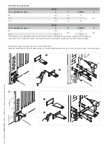
Page 39: ...0 120 220 100 Plus l angle d ouverture du vantail est élevé plus la vitesse d ouverture augmente et moins importante est la poussée du motoréducteur Plus l angle d ouverture du vantail se réduit plus la vitesse d ouverture diminue et plus importante est la poussée du motoréducteur Assembler et souder les deux parties de l étrier pilier Fixer l étrier au point prévu à l aide de chevilles et de vis ...

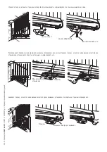
Page 40: ... cale supplémentaire de 10 mm entre le portail et la bride Introduisez la bague graissée dans le trou de l étrier pilier L étrier est muni de trous qui permettent de varier l angle d ouverture du portail Fixez la queue à articulation à l étrier N B sur les portes qui ne sont pas en métal assemblez et soudez les deux parties de l étrier et fixez les avec les vis appropriées Queue à articulation Bagu...

Page 41: ...utée avec la broche d attache et fixez le Broche d attache Ouvrez la porte et introduisez la broche dans l étrier portail et fixez la avec la rondelle et l écrou Étrier portail Débloquez le motoréducteur voir paragraphe déblocage manuel mettez la porte en position d ouverture maximale desserrez les écrous de l arrêt mécanique d ouverture placez le en butée avec la broche d attache et fixez le Broche ...

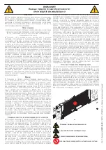
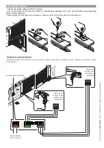
Page 42: ... Motoréducteur 24V d c à action retardée en fermeture Connexion motoréducteur 24V d c à action retardée en ouverture Armoire de commande ZLJ24 DÉBLOCAGE DU MOTORÉDUCTEUR Mettre hors tension avant d effectuer cette opération Le déblocage manuel du motoréducteur peut provoquer un mouvement incontrôlé du portail si ce dernier présente des problèmes mécaniques ou s il n est pas équilibré Connexions à ...

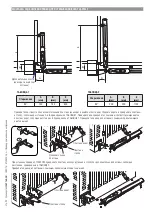
Page 43: ...is appropriées toujours en respectant la mesure E tableau 1 Enfin fixez le motoréducteur aux brides avec les vis et les rondelles en dotation Bride supplémentaire non fournie TABLEAU 1 TABLEAU 2 Ouverture A mm B mm E mm 90 130 130 800 Ouverture A mm B mm E mm 90 200 220 1100 Pour les motoréducteurs AX5024 fixez directement la bride de série au pilier sans utiliser la bride supplémentaire et tenez com...

Page 44: ...ION DES PROBLÈMES PROBLÈMES CAUSES POSSIBLES SOLUTIONS Le portail ne s ouvre pas et ne se ferme pas Défaut d alimentation Le motoréducteur est débloqué La batterie de l émetteur est déchargée L émetteur est cassé Le bouton d arrêt est bloqué ou cassé Le bouton d ouverture fermeture ou le sélecteur à clé sont bloqués Contrôler l alimentation secteur Bloquer le motoréducteur Remplacer les piles S ad...

Page 45: ...TIEN Entretien périodique Avant toute autre opération d entretien il est conseillé de mettre hors tension pour éviter toute situation de danger provoquée par des déplacements accidentels du dispositif Registre d entretien périodique tenu par l utilisateur semestriel Date Remarques Signature ...

Page 46: ...ffectuée _____________________________________________________________________________________ ____________________________________________________________________________________________________ _______________________________________________________________________________________________ Cachet installateur Nom opérateur Date intervention Signature technicien Signature client Intervention effec...

Page 47: ...lecte différenciée pour le recyclage Avant d effectuer ces opérations il est toujours recommandé de vérifier les normes spécifiques en vigueur sur le lieu d installation NE PAS JETER DANS LA NATURE ÉLIMINATION DU PRODUIT Nos produits sont réalisés à partir de différents matériaux La plupart de ces matériaux aluminium plastique fer câbles électriques sont assimilables aux déchets urbains solides Il...

Page 48: ...0 Dosson di Casier Treviso Italy tel 39 0422 4940 fax 39 0422 4941 Manuel FA01165 FR 05 2018 CAME S p A Traduction des instructions originales Le contenu de ce manuel est susceptible de subir des modifications à tout moment et sans aucun préavis ...

Page 49: ...AX3024 AX5024 RU Pусский FA01165 RU Привод для распашных ворот РУКОВОДСТВО ПО УСТАНОВКЕ ...

Page 50: ...АТЕЛЕЙ ОСТАВЛЯЙТЕ СВОБОДНЫМ И ЧИСТЫМ УЧАСТОК ДВИЖЕНИЯ ВОРОТ СЛЕДИТЕ ЗА ТЕМ ЧТОБЫ В ЗОНЕ ДЕЙСТВИЯ ФОТОЭЛЕМЕНТОВ НЕ БЫЛО РАСТИТЕЛЬНОСТИ И ПРЕПЯТСТВИЙ ДЛЯ ДВИЖЕНИЯ ВОРОТ НЕ ПОЗВОЛЯЙТЕ ДЕТЯМ ИГРАТЬ С ПЕРЕНОСНЫМИ ИЛИ ФИКСИРОВАННЫМИ УСТРОЙСТВАМИ УПРАВЛЕНИЯ ИЛИ НАХОДИТЬСЯ В ЗОНЕ ДВИЖЕНИЯ ВОРОТ НЕОБХОДИМО ДЕРЖАТЬ БРЕЛОКИ ПЕРЕДАТЧИКИ И ДРУГИЕ УСТРОЙСТВА УПРАВЛЕНИЯ В НЕДОСТУПНОМ ДЛЯ ДЕТЕЙ МЕСТЕ ВО ИЗБЕЖАНИЕ...

Page 51: ...щий особого внимания Этот символ обозначает раздел связанный с вопросами безопасности Этот символ обозначает раздел предназначенный для ознакомления конечного пользователя Масса створки кг Ширина створки м На распашных воротах настоятельно рекомендуется устанавливать электрозамок для обеспечения надежного закрытия створок Если используется самоблокирующийся привод монтаж электрозамка является обяз...

Page 52: ...м Основные компоненты 1 Привод 2 Пластина столба 3 Пластина ворот 4 Винт M8 x 35 UNI 5737 для крепления пластины столба 5 Втулка 6 Гайка M8 UNI 5588 для крепления пластины столба 7 Кабельный ввод 8 Механический упор 9 Винты M6 x 20 UNI 5739 для механического упора 10 Ось червяка 11 Шайба Ø 8 x 24 UNI 6593 12 Винт для крепления пластины ворот к оси M8 x 10 UNI 5739 13 Крепежная пластина 14 Дверца р...

Page 53: ...адает достаточной прочностью Для подключения к сети электропитания необходимо предусмотреть автоматический выключатель с расстоянием между контактами не менее 3 мм Убедитесь в том чтобы между внутренними соединениями кабеля обеспечивающими непрерывность контура безопасности и другими токопроводящими частями была предусмотрена дополнительная изоляция Приготовьте лотки и каналы для проводки кабеля г...

Page 54: ...я 230 В H05RN F 3G x 1 5 mm2 3G x 2 5 mm2 Электропитание двигателя 24 В FROR CEI 20 22 CEI EN 50267 2 1 4G x 1 5 mm2 4G x 2 5 mm2 Сигнальная лампа 2 x 0 5 mm2 Фотоэлементы передатчики 2 x 0 5 mm2 Фотоэлементы приемники 4 x 0 5 mm2 Устройства управления и безопасности 2 x 0 5 mm2 Антенна RG58 max 10 m Если длина кабеля отличается от приведенной в таблице его сечение определяется на основании реальн...

Page 55: ... B С МАКС E 90 200 220 150 1100 120 220 100 Чем больше угол открывания створки тем больше скорость открывания и тем меньше толкающее усилие привода Чем меньше угол открывания створки тем меньше скорость открывания и тем больше толкающее усилие привода При помощи сварки соедините две части заднего кронштейна Закрепите кронштейн на столбе в выбранном месте с помощью дюбелей и винтов или если столб м...

Page 56: ...астине Важное примечание если створки ворот неметаллические соберите и приварите два элемента пластины и зафиксируйте их с помощью соответствующих винтов Приварите пластину ворот к створке с учетом указанных в таблице расстояний Важное примечание при монтаже привода 001AX5024 необходимо вставить дополнительную уплотнительную прокладку толщиной 10 мм между воротами и пластиной Шарнир хвостовой част...

Page 57: ...упор закрывания Стержень Откройте створку вставьте стержень в отверстие пластины ворот и зафиксируйте его с помощью шайбы и гайки Пластина ворот Разблокируйте привод см параграф про ручную разблокировку полностью откройте створку ослабьте гайки механического упора открывания установив его впритык к стержню и зафиксируйте его Механический упор открывания Стержень Винт UNI 5739 M8 x 10 Шайба UNI 659...

Page 58: ...Ручная разблокировка привода может привести к неожиданному движению ворот если они повреждены или надлежащим образом несбалансированы Подключение к блоку управления Внимание Перед началом работ по эксплуатации ремонту настройке и регулировке блока управления отключите сетевое электропитание Электропитание 230 В 50 60 Гц Подключение привода 24 В с замедленным закрыванием Подключение привода 24 В с ...

Page 59: ...крепите с помощью соответствующих винтов пластину ворот соблюдая расстояние Е приведенное в ТАБЛИЦЕ 1 Прикрепите привод к пластинам с помощью прилагающихся винтов и шайб Открывание A мм B мм E мм 90 200 220 1100 ТАБЛИЦА 1 ТАБЛИЦА 2 Дополнительная пластина не входит в комплект поставки При установке привода 001AX5024 прикрепите пластину непосредственно к столбу без дополнительной пластины соблюдая ...

Page 60: ...ВНОСТЕЙ НЕИСПРАВНОСТЬ ВОЗМОЖНАЯ ПРИЧИНА СПОСОБЫ УСТРАНЕНИЯ Ворота не открываются и не закрываются Отключено электропитание Разблокирован привод Разрядились батарейки брелока передатчика Сломан брелок передатчик Кнопка Стоп заедает или сломана Кнопка открывания закрывания или ключ выключатель заедает Включите электропитание Заблокируйте привод Поменяйте батарейки Обратитесь к установщику Обратитесь...

Page 61: ...ческое техническое обслуживание Перед выполнением работ по техническому обслуживанию отключите питание во избежание возникновения опасных ситуаций вызванных непроизвольным движением устройства Журнал периодического технического обслуживания заполняемый пользователем каждые 6 месяцев Дата Выполненные работы Подпись ...

Page 62: ...__________________ Место печати Компания Дата проведения работ Подпись установщика Подпись заказчика Выполненные работы ____________________________________________________________________________________ __________________________________________________________________________________________________ Место печати Компания Дата проведения работ Подпись установщика Подпись заказчика Выполненные ра...

Page 63: ...ить в соответствии с действующим законодательством местности в которой производилась эксплуатация изделия НЕ ЗАГРЯЗНЯЙТЕ ОКРУЖАЮЩУЮ СРЕДУ УТИЛИЗАЦИЯ ИЗДЕЛИЯ Наши продукты изготовлены с использованием различных материалов Бóльшая их часть алюминий пластмасса сталь электрические кабели ассимилируется как городские твердые отходы Они могут быть переработаны специализированными компаниями Другие компо...

Page 64: ...31030 Dosson di Casier Treviso Italy tel 39 0422 4940 fax 39 0422 4941 Руководство FA01165 RU 05 2018 CAME S p A Перевод оригинальных инструкций Содержание данного руководства может быть изменено в любое время без предварительного уведомления ...

Reviews: