LINE
FUSE
ON
2
1
3 4 5 6 7 8 9 10
L1T L2T CT VS VF
U
V
W E1
L
N
24
12
0
10 11
TS
1
2
3
3P
4
7
C1 C3
EB EB
FC FA
F
+ A. C.T. -
+ PAR.OP -
ELECTRIC
BLOCK
1.6A
BOARD 315mA
ACCESSORIES
1A
BATTERY 1.6A
CONTROL
BOARD
ZBK8
AF1
AF2
CH1
-
+
18
5
12
14
1
16
6
7
4
8
9
10
11
17
15
3
13
2
p.
1
0
10
- M
an
u
al
:
F
A
0
0
6
0
5
-E
N
FA
0
0
6
0
5
-E
N
v.
1
- 0
1/
2
0
17 - © C
A
M
E S
.p.
A
. - T
h
e c
onte
nts of th
is
m
an
u
al
m
ay b
e c
h
an
g
ed, at a
ny ti
m
e, a
n
d w
ith
ou
t n
oti
ce
.
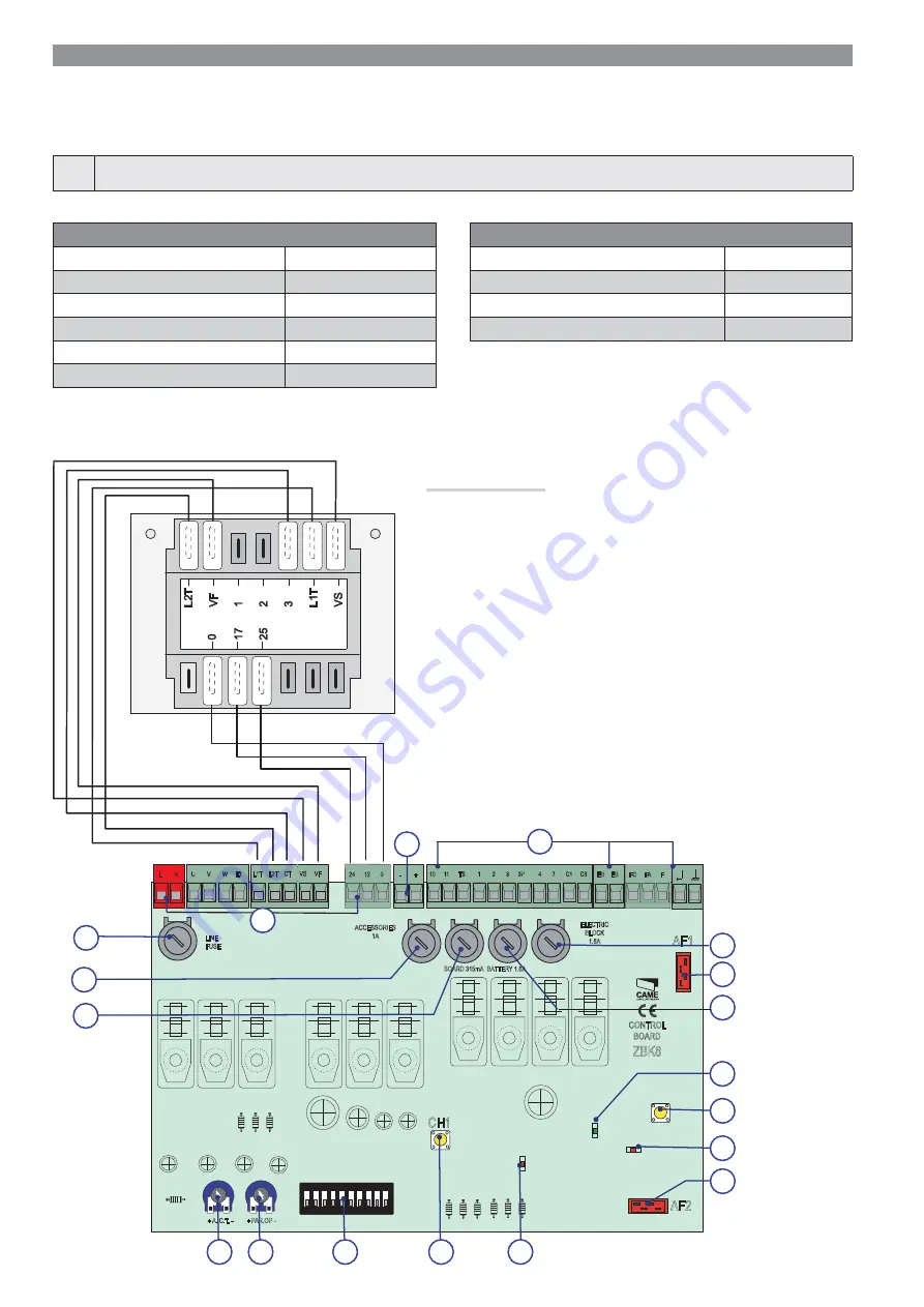
Description of parts
1. Terminals for connecting to
the power supply and the
transformer
2. Line fuse 8 A
3. Accessories fuse 1 A
4. DIP-switch "selecting functions”
5. Radio-frequency card slot for
remote control
6. A.C.T. Trimmer: adjusting the
automatic closing time
7. PAR.OP Trimmer .: adjusting
partial opening
8. Code-memorizing button on the
radio remote-control
9. Radio remote-control code
signaling LED
10. Battery-connection terminal
11. Radio frequency card slot for
Pratico System
12. Battery fuse 1.6 A
13. Control unit fuse 315 mA
14. Electric lock fuse 1.6 A
15. Signal LEDs 230 V
16. Electric lock, limit switch and
accessory connection terminals
17. PRATICO SYSTEM radio code
signal LED
18. Button for memorizing the
PRATICO SYSTEM radio code
ZBK8 TECHNICAL DATA
Power supply voltage 230 V - 50/60 Hz
Absorption when idle 38 mA
Accessories' maximum power load 24 V 40 W
Circuits insulation class II
ZBK8 FUSE TABLE
to protect: fuse rated:
Control board (line) 8 A-F
Accessories 1 A-F
Control devices (control unit) 315 mA-F
Electroblock 1.6 A-F
Batteries 1.6 A-F
ELECTRICAL CONNECTIONS
⚠
Warning! Before doing any work on the control board, cut off the mains power supply, and disconnect any batteries.
Power supply to the control panel and control devices: 24 V AC/DC.
Use DIP switches to set functions and the trimmer for adjustments.
All connections are quick-fuse protected.
⚠
The operator is designed to be fitted on the left. If installing on the right, invert the gearmotor's U-V and the limit-switches FA-FC cables.


