background image

Page 

19

 - Manual 

FA01295-EN

  - 03/2023 - © C

AME S.p.A. - The contents of this manual may be changed at any time and without notice. - T

ranslation of the o

riginal instructions

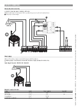
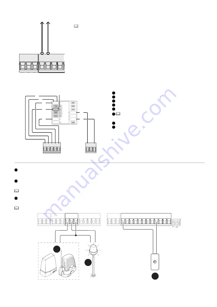
Power supply output for accessories

10  11  TS   1   

24V       0

The output normally delivers 24 V AC.

 The sum of the power draw for the connected accessories must not exceed 20 W.

Torque limiter

L1T L2T CT VS VF

24V       0

0

17

24

FR

1

2

3

4

SP

0

1

2

3

4

5

8

7

6

1

 Grey cable

2

 Brown cable

3

 Red cable

4

 Black cable

5

 White cable

6

 To vary the motor torque, move the corresponding Faston terminal to 

one of the four positions; from 1 (minimum) to 4 (maximum).

7

 Blue cable

8

 Orange cable

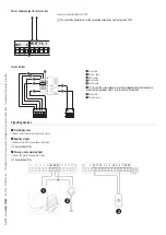
Signalling devices

1

 Flashing beacon

It flashes when the operator opens and closes.

2

 Additional light

It increases the light in the manoeuvring area.

 See function [F18].

3

 Passage-open warning light

It notifies the user of the operator status.

 See function [F10].

2

1

3

L

N

U V W

E1 EX W

24V

O

10 11 TS 1

2

3 3P 4

5

7 CX CY

L1T L2T CT VS VF

L

N

U V W

24V

O

L1T L2T CT VS VF

Summary of Contents for BKS08AGS

Page 1: ...Sliding gate operators BKS08AGS BKS22AGS BKS12ALS BKS12AGS BKS18RGS BKS18ALS BKS18AGS BKS08ALS BKS22ALS INSTALLATION MANUAL FA01295 EN EN Italiano...

Page 2: ...Page 2 Manual FA01295 EN 03 2023 CAME S p A The contents of this manual may be changed at any time and without notice Translation of the original instructions 2 3 1 2 3 1...

Page 3: ...revent any mechanical hazards due to persons loitering within the operating range of the operator The electrical cables must pass through special pipes ducts and cable glands in order to guarantee ade...

Page 4: ...lease follow these brief disposal guidelines DISPOSING OF THE PACKAGING The packaging materials cardboard plastic etc can be disposed of easily as solid urban waste separated for recycling Before dism...

Page 5: ...decoder and mechanical limit switches for sliding gates up to 2200 kg in weight and 20 m in length RAL7024 grey cover 801MS 0110 BKS18RGS 120 V AC operator complete with electronic board with programm...

Page 6: ...original instructions Description of parts Operator 1 Cover 2 Front cover 3 Gearmotor 4 Fan 5 Capacitor 6 Mechanical limit switch 7 Anchoring plate 8 Control board holder 9 Control board 10 Limit swit...

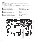
Page 7: ...connecting the gearmotor 3 Terminal board for connecting the signalling devices 4 Terminal board for connecting the transformer 5 Control board fuse 6 Accessories fuse 7 Terminal board for connecting...

Page 8: ...nslation of the original instructions Size 183 143 326 x a m 2 2 359 5 5 0 1 109 5 170 262 Usage limitations MODELS BKS08AGS BKS12AGS BKS18AGS BKS22AGS BKS18RGS BKS08ALS BKS12ALS BKS18ALS BKS22ALS Max...

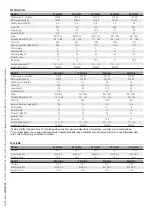
Page 9: ...andby consumption W 4 5 4 5 4 5 4 5 Power W 520 380 480 580 Capacitor F 25 25 31 5 35 Current draw A 4 5 3 3 4 2 5 1 Colour RAL 7040 RAL 7040 RAL 7040 RAL 7040 Operating temperature C 20 55 20 55 20 5...

Page 10: ...3 MODELS BKS08AGS BKS12AGS BKS18AGS BKS22AGS BKS18RGS Cycles hour no 14 14 14 14 14 Consecutive cycles no 13 13 13 13 13 MODELS BKS08ALS BKS12ALS BKS18ALS BKS22ALS Cycles hour no 14 14 14 14 Consecuti...

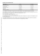
Page 11: ...ing to the motor power and cable length When operating at 230 V and outdoors use H05RN F cables compliant with 60245 IEC 57 IEC when indoors use H05VV F cables compliant with 60227 IEC 53 IEC For powe...

Page 12: ...iminary operations Dig a hole for the foundation frame Set up the corrugated tubes needed for the wiring coming out of the junction pit For connecting the gearmotor we suggest using a 40 mm corrugated...

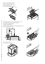
Page 13: ...plate in the iron cage The tubes must pass through the existing holes 2 1 UNI 5739 12 X 70 M12 Position the anchoring plate taking note of the measurements shown in the drawing If the gate does not h...

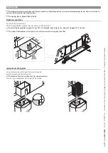
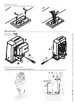
Page 14: ...les into the tubes until they protrude by about 600 mm Setting up the operator Remove the front cover 1 2 3 Remove the operator cover 4 5 Place the operator on top of the anchoring plate The electrica...

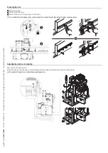
Page 15: ...3 Weld or fasten the rack to the gate along its entire length To assemble the rack modules use an extra piece and rest it under the joint then fasten it in place using two clamps Adjusting the pinion...

Page 16: ...operator in place Only fasten the operator after adjusting the pinion rack coupling Fasten the operator to the anchoring plate using stoppers and nuts Establishing the limit switch points 1 Open the...

Page 17: ...ay be changed at any time and without notice Translation of the original instructions 4 Close the gate 5 Insert the closing limit switch tab in the rack The spring must trigger the microswitch 6 Faste...

Page 18: ...ble glands on the board holder 10 11 TS 1 L N U V W E1 EX W L1T L2T CT VS VF 24V 0 0 17 24 FR 1 2 3 4 SP 0 120 230 V AC 50 60 Hz 1 2 3 4 5 8 9 7 6 Power supply Make sure the mains power supply is disc...
Page 19: ...4 5 8 7 6 1 Grey cable 2 Brown cable 3 Red cable 4 Black cable 5 White cable 6 To vary the motor torque move the corresponding Faston terminal to one of the four positions from 1 minimum to 4 maximum...

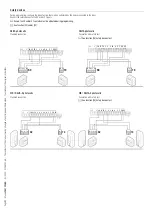
Page 20: ...act is being used it must be activated during programming See the F1 Total stop function 5 Control device NO contact Open command When the F6 Hold to run function is active a control device must be se...

Page 21: ...be activated during programming See function F2 and or F3 DELTA photocells Standard connection DELTA photocells Connection with safety test See function F5 Safety devices test 24V O 10 11 TS 1 2 3 3P...

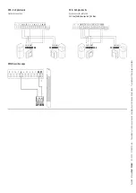
Page 22: ...structions DXR DLX photocells Standard connection DXR DLX photocells Connection with safety test See Safety devices test function RX TX 10 11 OUT 10 11 SY 24V O 10 11 TS 1 2 3 3P 4 5 7 CX CY 24V O RX...

Page 23: ...sing photocells C2 Reclose while opening photocells C3 Partial stop Only with Automatic close activated Photocells C4 Obstacle standby photocells C7 Reopen while closing sensitive edges C8 Reclose whi...

Page 24: ...is open The light flashes every second when the gate is closing and remains off when the gate is closed Sensor type Choose the type of control device F14 Sensor type 1 Keypad selector default 0 Trans...

Page 25: ...ve data OFF Default ON Run operation Read data Upload user data timings and configurations to the memory device memory roll The function is displayed only when a memory roll card is inserted into the...

Page 26: ...utomatic close activated P4 Obstacle standby RIO PH T2 Associate one of the available functions with a wireless safety device The function only appears if the RIO CONN interface board is present F68 R...

Page 27: ...the functions Radio decoding Motor type and the settings related to travel calibration A4 Parameter reset OFF Default ON Manoeuvre counter View the number of operator manoeuvres The number of manoeuvr...

Page 28: ...AGES E4 Service test failure error E7 Operating time error E8 Open release hatch error E9 Obstacle detected during closing E10 Obstacle detected during opening E11 The maximum number of obstacles dete...

Page 29: ...e see the ELECTRICAL CONNECTIONS section CAT5 A B GND A B GND RSE 1 2 3 4 1 2 3 4 RSE RSE MASTER SLAVE Programming All programming operations described below must be performed only on the control boar...

Page 30: ...Page 30 Manual FA01295 EN 03 2023 CAME S p A The contents of this manual may be changed at any time and without notice Translation of the original instructions...

Page 31: ...Page 31 Manual FA01295 EN 03 2023 CAME S p A The contents of this manual may be changed at any time and without notice Translation of the original instructions...

Page 32: ...contents of this manual may be changed at any time and without notice Translation of the original instructions CAME S p A Via Martiri della Libert 15 31030 Dosson di Casier Treviso Italy Tel 39 0422...

Reviews: