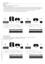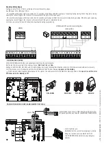
10 11 TS 1 2 3 3P 4 5 7 CX CY
L N U V W E1 EX W L1T L2T CT VS VF
24V 0
FC FA F
p.
14
- M
anu
al
FA
0
1
2
0
8
-E
N
- 0
7/
2
0
21 - © C
A
M
E S
.p
.A
. - T
ransla
te
d o
riginal inst
ru
ct
io
ns
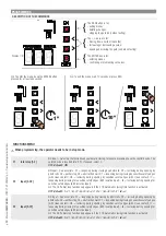
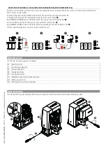
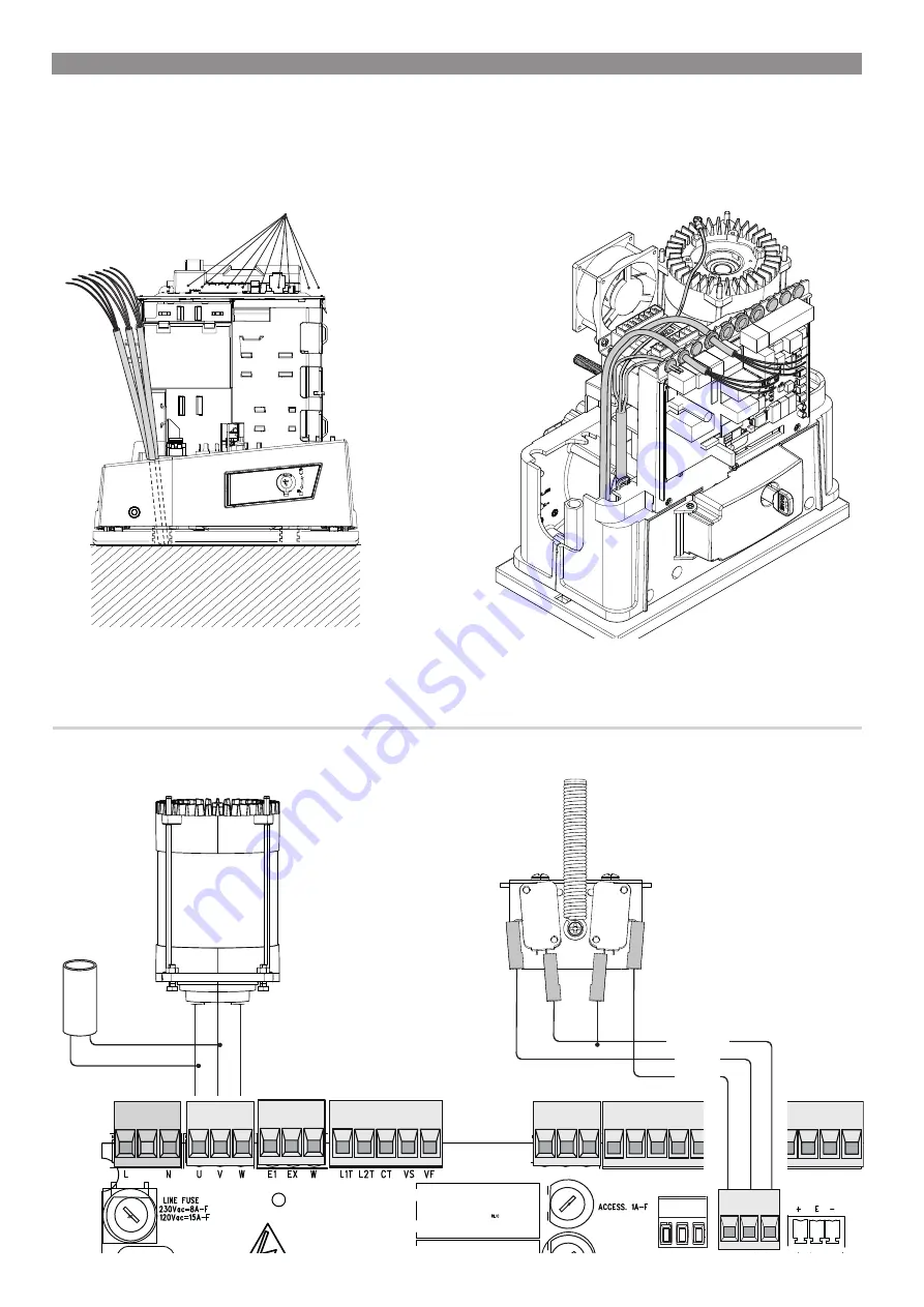
WHITE
RED
ORANGE
Mechanical limit switch
Opening limit-switch
micro-switch
Condenser
120/230V (AC) gear motor
Control-board brace cable glands
Closing limit-switch
micro-switch
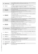
ELECTRICAL CONNECTIONS
⚠
Connect all wires and cables in compliance with the law.
Before connecting all the wires, set up the cables by using cable glands on the control board brace, as shown in the figure.
The electrical cables must not touch any heated parts such as the motor, transformer, and so on.
FACTORY WIRING


