7
7
7
7
Page
5
- Manual
FA01157-EN
- 09/2018 - © CAME S.p.A. - The contents of this manual may be changed, at any time, and without notice. - T
ranslation of the
original instructions
DUTY CYCLES
Datum
Cycles/hour (no.)
14 series
Consecutive cycles (no.)
17 series
The cycles calculation is for
standard-length gates
(see the intended use), that are professionally installed, free of any mechanical issues and/or accidental
friction points, and measured at 20° C, as stated in EN Standard 60335-2-103.
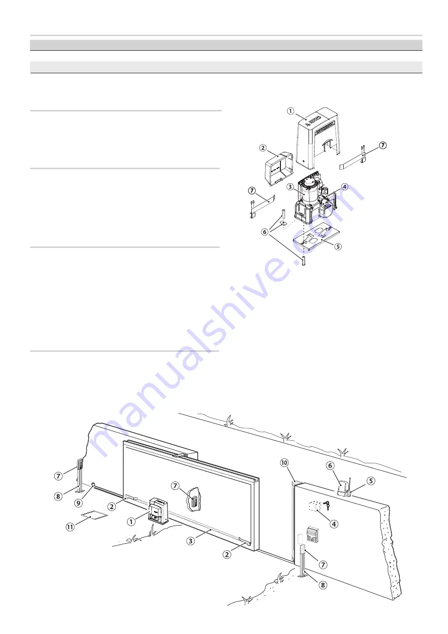
DESCRIPTION OF PARTS
1. Cover
2. Front
cover
3. Gearmotor
4. Mechanical limit switch
5. Anchoring
plate
6.
Fastening
hardware
7. Limit-switch
tabs
STANDARD INSTALLATION
1. Gearmotor
2. Limit-switch
fins
3. Rack
4. Key-switch
selector
5. Antenna(s)
6. Flashing
light
7. Photocells
8. Small
post
9. Mechanical gate stop
10. Sensitive safety-edge
11. Junction pit
CONTROL PANELS
002ZT6
Control panel with safety devices self-diagnosis.
002ZT6C
Control panel, complete with safety lock and buttons, with safety
devices self-diagnosis.
COMPLETION ACCESSORIES
❶
001B4353
Chain transmission device.
❷
009CCT
Simple 1/2” chain.
❸
009CGIU
1/2” chain coupling.
❹
001R001
Customized cylinder lock.
Page
5
- Manual
FA01
22
9-EN
- 10/2018 - © CAME S.p.A. - The contents of this manual may be changed, at any time, and without notice. - Original instructio
ns


