9
3
4
2
5
6
7
10
11
1
2
8
Pa
g.
4
- M
an
u
al
c
od
e:
11
9
B
T
8
5
11
9
B
T
8
5
ve
r.
2
04/
2
0
14 © C
A
M
E c
an
ce
lli
auto
m
ati
ci
s.p.a. - T
h
e d
ata a
n
d i
nf
or
m
ati
on r
ep
orte
d i
n th
is
in
sta
lla
tio
n m
an
u
al
a
re s
u
sc
ep
tib
le to
c
h
an
g
e at a
ny ti
m
e a
n
d w
ith
ou
t o
b
lig
ati
on
o
n C
A
M
E c
an
ce
lli
auto
m
ati
ci
s.p.a. to n
otify u
se
rs.
ENGLISH
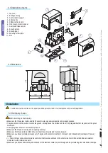
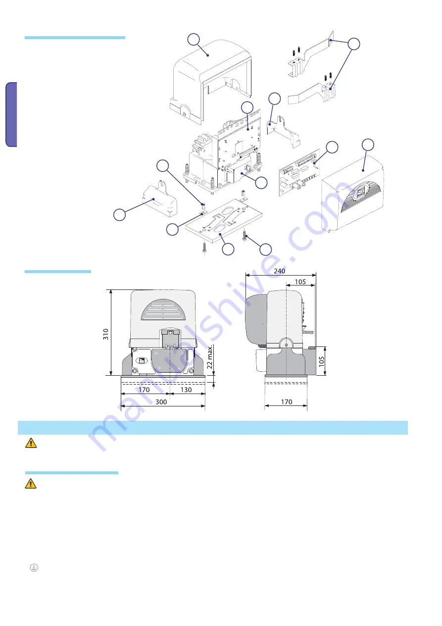
4.4 Dimensions
4.3 Description of parts
5 Installation
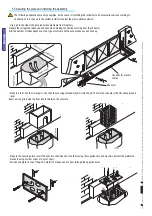
Installation must be carried out by expert qualified personnel and in full compliance with current regulations.
5.1 Preliminary checks
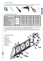
Before installing, do the following:
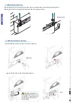
• Make sure that the gate is stable, and that the castors are in good working order and properly greased.
• The ground rack must be well secured to the ground, entirely above the surface and free of any irregularities that may obstruct the gate’s
movement.
• The upper guide rails must not create any friction.
• Make sure that there is a closing and an opening endstops.
• Make sure that the operator is attached to a solid surface and protected from any impacts;
• Make sure you have a suitable omnipolar cut-off device with contacts more than 3 mm apart, and independent (sectioned off) power
supply;
•
Check that any connections inside the container (that provide continuity to the safety circuit) are fitted with additional insulation
compared to other internal live parts;
• Make sure you have suitable tubing and conduits for the electrical cables to pass through and be protected against mechanical damage.
1 - Top cover
2 - Settings casing
3 - Control board support
4 - Endstop fins
5 - ZBX8 electronic card
6 - Front cover to control panel
7 - Gearmotor release door
8 - Securing plate
9 - Securing bolt
10 - Securing screw plate
11 - Nut


