Pa
g.
8
- M
an
u
al
c
od
e:
11
9
B
T
8
5
11
9
B
T
8
5
ve
r.
2
04/
2
0
14 © C
A
M
E c
an
ce
lli
auto
m
ati
ci
s.p.a. - T
h
e d
ata a
n
d i
nf
or
m
ati
on r
ep
orte
d i
n th
is
in
sta
lla
tio
n m
an
u
al
a
re s
u
sc
ep
tib
le to
c
h
an
g
e at a
ny ti
m
e a
n
d w
ith
ou
t o
b
lig
ati
on
o
n C
A
M
E c
an
ce
lli
auto
m
ati
ci
s.p.a. to n
otify u
se
rs.
ENGLISH
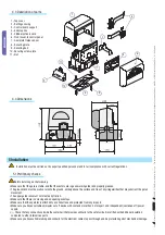
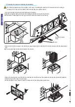
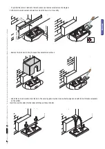
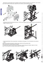
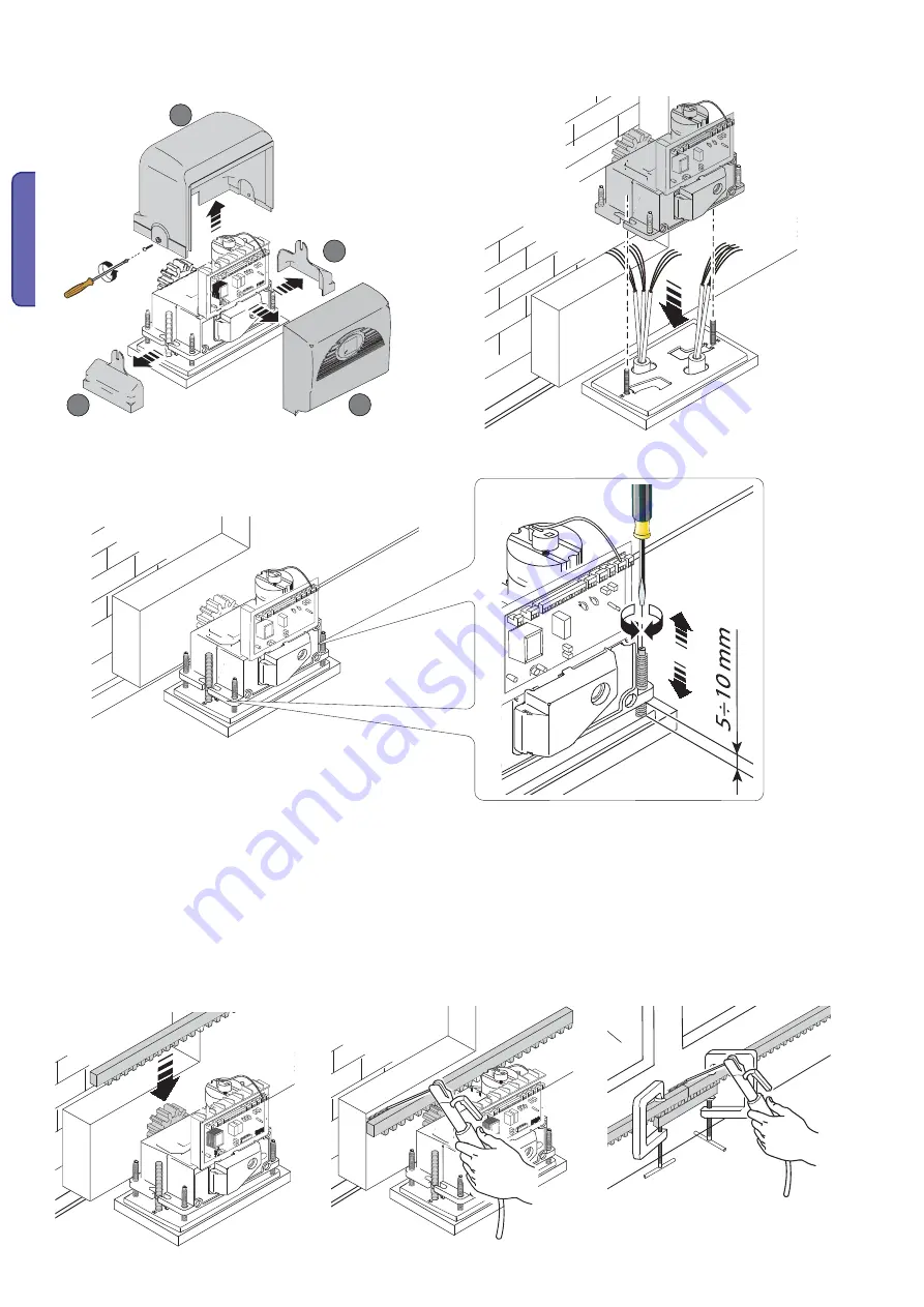
- Remove the cover from the gearmotor by loosening the side bolts, perforate the cable shafts using a screwdriver or a pair of scissors
and position the gearmotor atop the plate. Careful! The electric cables must pass through the cable shafts.
- Lift the gearmotor from the securing plate by about 5 to 10mm by using the threaded steel-levelling feet to allow any later adjustments
between the pinion and the rack.
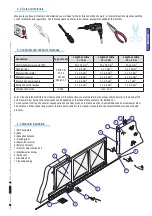
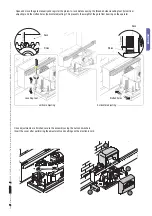
- The following illustrations for the securing the rack, are just examples of applications. It is up to the installer to choose the best
solution.
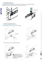
Releasing the gearmotor (see paragraph on manual release). Rest the rack on the gearmotor pinion.
Weld or secure the rack to the gate along its entire length.
To assemble the rack modules, use an excess piece of rack and place it under the joining point, then block it using two C-clamps.
Note: if a rack is already in place, then just adjust the pinion-to-rack distance.


