14
15
11
17
12
16
6
8
8
9
2
9
13
10
1
7
5
3
4
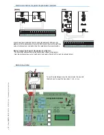
F U S E TA B L E Z B X - 1 0
To protect: fuse:
Control board (line) 3.15A-F
Accessories 1.6A-F
Command devices 1A-F
T E C H N I C A L I N F O R M AT I O N
Power supply 230V - 50/60 Hz
Maximum power allowed 300 W
Absorption at rest 110 mA
Maximum power for 24V accessories 37 W
Use 230V A.C. to power the electronic card using the L-N terminals, at a max 50/60Hz frequency.
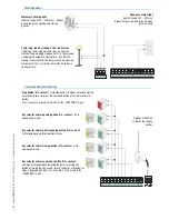
Use 24V to power the command devices and accessories. Careful! The accessories cannot exceed 37W of overall power.
All connections are protected by quick-fuses – see table.
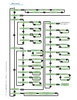
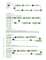
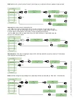
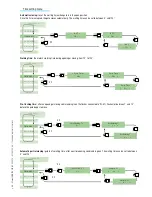
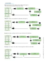
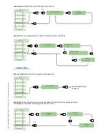
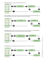
The input and output contact functions, the timing settings and users’ management, are set and viewed on the display, which is run by
software.
Warning! Before acting on the machinery, cut off the main power supply and disconnect any emergency batteries.
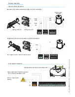
Control board
General description
1) Display
2) Card fuse
3) Accessory fuse
4) Line fuse
5) AF card coupling for remote control
6) RSE card coupling for paired connections
7) 230V-power signalling LED
8) Connecting terminal board
9) Transformer-connecting terminal board
10) Programming buttons
11) Display lighting adjustment trimmer
12) Memory roll board connector
13) Power supply terminals
14) Motor terminals
15) Antenna terminals
16) Encoder terminals
17) Endstop terminals
Main components
p.
11
- M
anu
al
FA
0
1
1
3
7
-E
N
- 0
4
/2
0
18 - © C
A
M
E S
.p
.A
. - T
ransla
te
d o
riginal inst
ru
ct
io
ns


