23
TEST PHOTOELECTRIC SENSORS
Each open/close command, the electronic card verifies the photoelectric
sensors are connected and working. Any problems with the photoelectric
sensors will cause the (PROG) LED to flash on the electronic card, which
cancels any commands from the remote control or push-button.
1
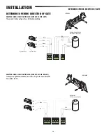
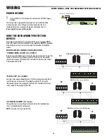
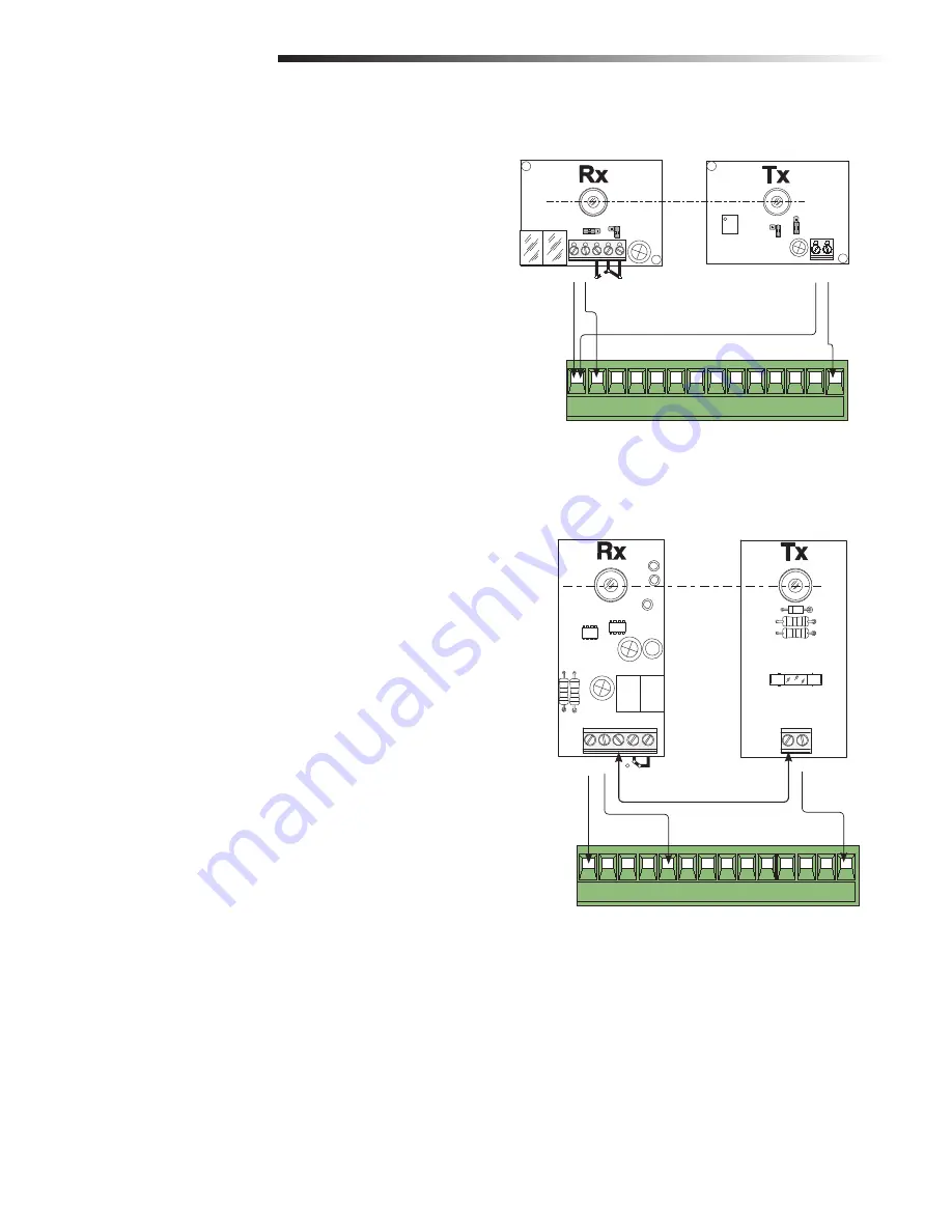
Electrical connection to operate the photoelectric sensors safety test:
• Connect the transmitter and receiver as shown in the diagram.
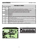
• Set DIP switch 7 to ON to activate the test.
2
When the safety test function is activated, the N.C. contacts:
• If unused--are to be excluded on their relative DIP switches (see
“Functionality Switches”).
48
48 #
.#
% 0
# # # # 43
./
.#
#
% 0
# # # # 43
(DIR10)
(DOC)
ADJUSTMENT
TEST PHOTOELECTRIC SENSORS

