Page
15
- Manual
FA02036-EN
- 12/2023 - © C
AME S.p.A. - The contents of this manual may be changed at any time and without notice. - T
ranslation of the o
riginal instructions
4
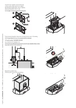
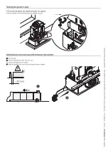
Close the gate.
5
Insert the closing limit-switch tab in the rack.
The spring must trigger the microswitch.
6
Fasten the closing limit-switch tab using the grub screws supplied.
~ 20
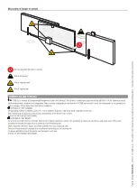
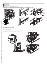
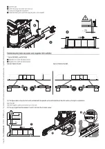
Establishing the travel end points with magnetic limit switches*
* Only for BXV06AGL and BXV10AGL
A
Magnetic limit-switch tab during closing
B
Magnetic limit-switch tab during opening
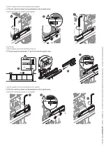
Operator fitted on the left
Operator fitted on the right.
The figures below show the limit switch installed with the operator on the left.Installation of the limit switch on the right is symmetrical.
Open the gate.
Insert the magnetic opening limit-switch tab on the rack.
The tab magnet must be between 10 and 30 mm from the magnetic sensor.
~ 20
10 < 30


