Page
18
- Manual
FA02036-EN
- 12/2023 - © C
AME S.p.A. - The contents of this manual may be changed at any time and without notice. - T
ranslation of the o
riginal instructions
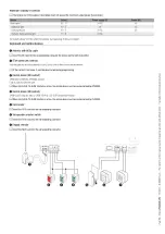
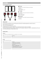
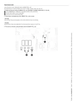
Maximum capacity of contacts
The total power of the outputs listed below must not exceed the maximum output power [Accessories]
Device
Output
Power supply (V)
Power (W)
Accessories
10 - 11
24 AC
40
Additional light
10 - E
24
25
Flashing beacon
10 - E
24 AC
25
Operator status warning light
10 - 5
24 AC
-
The outputs deliver 24 V DC when the batteries start operating, if they are installed.
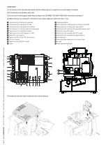
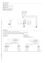
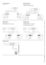
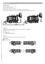
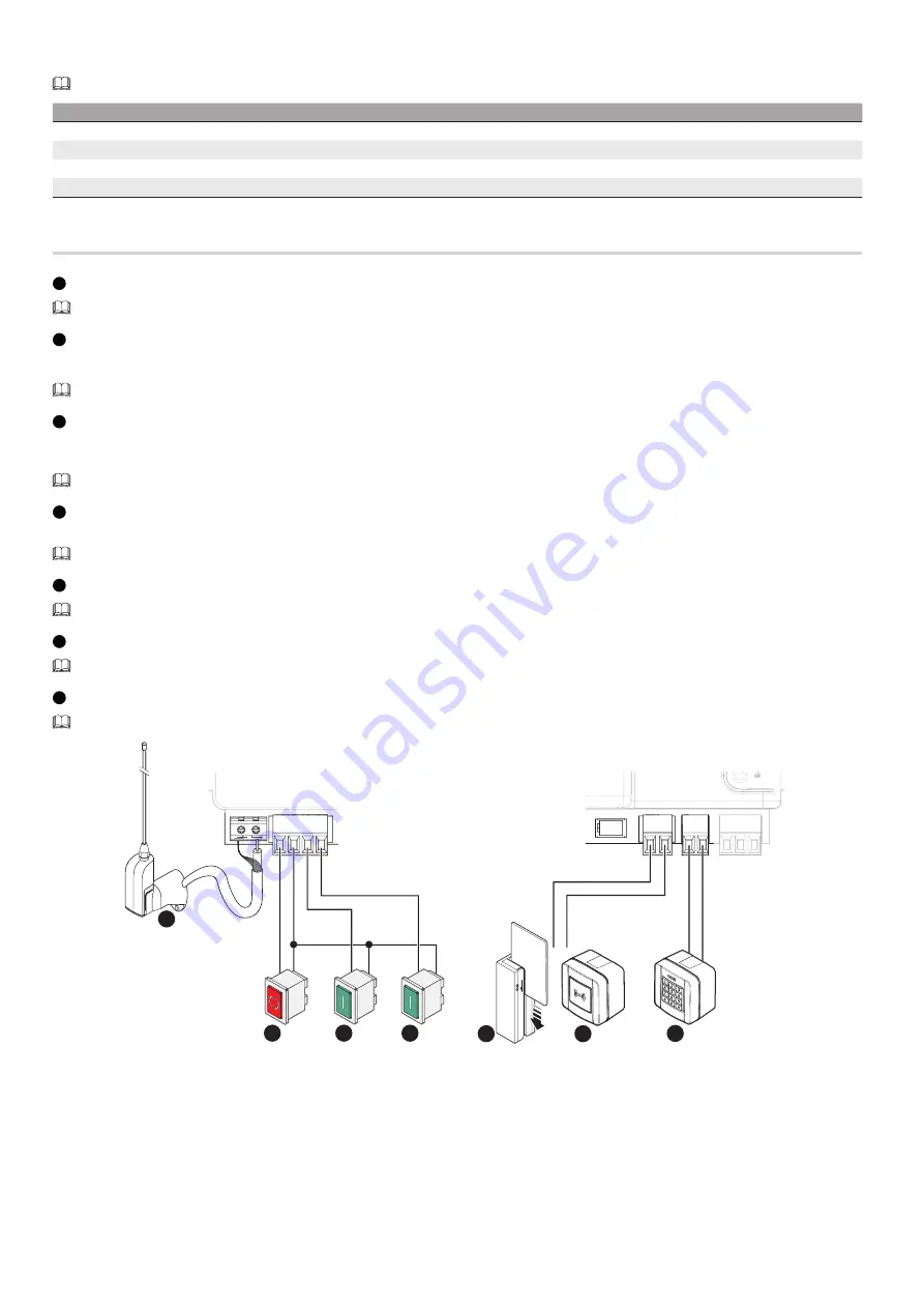
Command and control devices
1
Antenna with RG58 cable
Insert the AF card into the corresponding connector for remote control with transmitter.
2
STOP button (NC contact)
Stop the gate and exclude automatic closing. Use a control device to resume movement.
If the contact is not used, it must be deactivated during programming.
3
Control device (NO contact)
OPEN ONLY or PARTIAL OPENING function
Fully or partially open the gate.
When the [HOLD-TO-RUN] function is active, the control device must be connected during OPENING.
4
Control device (NO contact)
OPEN-CLOSE (step-by-step) or OPEN-STOP-CLOSE-STOP (sequential) function
When the [HOLD-TO-RUN] function is active, the control device must be connected during CLOSING.
5
Card reader
Insert the R700 card into the corresponding connector.
6
Transponder selector switch
Insert the R700 card into the corresponding connector.
7
Keypad selector
Insert the R800 card into the corresponding connector.
A B GND
A B
S1 GND
1 2 3P 7
A B GN
B
D
2
3
4
7
6
5
1

