3
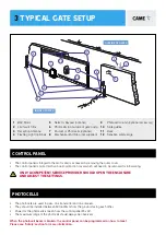
TYPICAL GATE SETUP
PHOTOCELLS
• The photocells are used in pairs, one transmitter and one receiver.
• They should be installed between 500-600mm from the ground, facing each other.
• Power for the photocells is taken from the control panel 24v AC.
• The maximum range of the photocell should always be observed.
When the photocell beam is broken, the control panel can be programmed on how to react.
Please see ‘Safety’ section for more information.
1
9
7
8
2
5
3
4
6
OUTSIDE OF GATES
INSIDE OF GATES
10
11
12
8
1
BXV Motor
5
Selector Keypad (optional)
9
Photocell column (optional accessory)
2
Limit switch fins
6
Photocells (on outside of gate posts)
10
Slide guides
3
Reception Antenna
7
2nd set of Photocells (optional)
11
Rack
4
Flashing Light (optional)
8
Mechanical End Stop (not supplied)
12
Sensitive safety-edge
CONTROL PANEL
• The control panel is integral to the motor and is accessed by removing the outer cover.
• The control panel is protected by a board-protection cover which will need to be removed for initial wiring.
Only a competent service provider should open the enclosure
and adjust the settings.


