background image

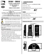
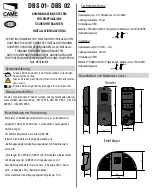
Trasmettitore

Ricevitore

Progettato e costruito interamente dalla CAME Cancelli Automatici 

S.p.A. Garantito 24 mesi salvo manomissioni

Predisposto per automatismi serie BZ-BX-BK.

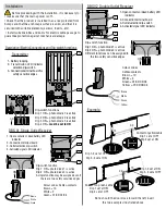
Dispositivo di protezione ad infrarossi composto da:

- Trasmettitore alimentato a batterie  con DIP per selezione funzioni.

- Ricevitori 24V. AC/DC (DBS01 con contatto relè interbloccato, 

ad uscita singola), (DBS02, ad uscita doppia), con possibilità di 

collegamento per test servizi. 2 LED di segnalazione canale attivo, 2 

led di segnalazione batteria scarica.

-Distanza massima Trasmettitore /Ricevitore 10 m

Caratteristiche tecniche

                        Questo simbolo segnala parti da leggere con attenzione.

                         Questo simbolo segnala parti riguardanti la sicurezza

.


Questo simbolo segnala le note da comunicaall’utente.

Per il prodotto in oggetto sono state considerate le seguenti nor-
mative di riferimento: EN 12978, UNI EN 954-1, CEI EN 60335-1, 
UNI EN 12453.


 “ISTRUZIONI IMPORTANTI PER LA SICUREZZA DURANTE

L’INSTALLAZIONE”

ATTENZIONE: L’INSTALLAZIONE NON CORRETTA PUÒ CAUSARE 

GRAVI DANNI SEGUIRE TUTTE LE ISTRUZIONI DI INSTALLAZIONE

IL PRESENTE MANUALE È DESTINATO SOLAMENTE A

INSTALLATORI PROFESSIONALI O A PERSONE COMPETENTI.

 Legenda simboli

 Riferimenti normativi

Descrizione dispositivo

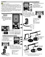
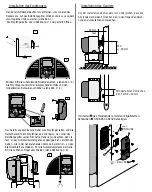
Ingombri e misure fori

Trasmettitore

Tensione di Alimentazione: 6 V 

(4 batterie da 1.5V AAA)

Assorbimento : 70 

μ

A

Grado di protezione: IP54

Materiale:PC-ABS UL94V0 / Policarbonato / Marpram mar TPA1 65 NT

Temperatura di esercizio:

—#

—#

Ricevitore

Tensione di Alimentazione: 24 V a.c. - d.c.

Assorbimento : 48 mA

Grado di protezione: IP54

Materiale:PC-ABS UL94V0 / Policarbonato / Marpram mar TPA1 65 NT

Temperatura di esercizio

:

—#

—#

I

DBS01 - DBS02

MANUALE D’INSTALLAZIONE

SISTEMA DI COMUNICAZIONE 

PER BORDI SENSIBILI DI 

SICUREZZA

Summary of Contents for DBS01

Page 1: ...tto in oggetto sono state considerate le seguenti nor mative di riferimento EN 12978 UNI EN 954 1 CEI EN 60335 1 UNI EN 12453 ISTRUZIONI IMPORTANTI PER LA SICUREZZA DURANTE L INSTALLAZIONE ATTENZIONE...

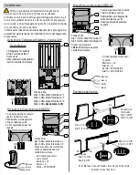
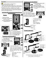
Page 2: ...sicurezza 4 3 2 1 K K K R13 R15 R22 R23 ON Funzione Dip Dip 1 in ON Attivo foto diodo n 1 Dip 2 in ON Attivo foto diodo n 2 Dip 3 in ON Attivo foto diodo n 3 Dip 4 in ON deve essere in ON 1 Led di se...

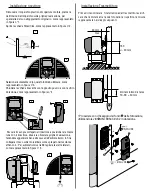
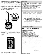
Page 3: ...a con il ricevitore dove era ubicata la griglia di aereazione facendola agganciare bene alla cassa dell automatismo in fine collegare il cavo sulla morsettiera come spiegato nella colonna affianco 4 P...

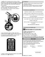
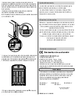
Page 4: ...l luogo di smaltimento NON DISPERDERE NELL AMBIENTE K K K 1 2 3 4 5 6 7 8 9 10 11 12 1 2 3 4 5 6 7 8 9 10 11 12 05 06 07 08 09 V1 V2 V3 05 06 07 08 09 V1 V2 V3 1 5V AAA 1 5V AAA 1 5V AAA 1 5V AAA R13...

Page 5: ...nterlocked relay contact with single outlet DBS02 with double outlet with connections available for testing operations 2 active channel LED indicators 2 dead battery LED indicators Maximum distance tr...

Page 6: ...ion LED indicator selection dip switch 3 Connectionterminalboardfor safety sensitive edges 4 3 2 1 K K K R13 R15 R22 R23 ON Dip switch functions Dip 1 ON photo diode 1 is active Dip 2 ON photo diode 2...

Page 7: ...with the Receiver where the aeration grid was located hooking it to the automatic system s case and then connect the cable to the terminal board as instructed in column 4 For BZ series automatic syste...

Page 8: ...tions in force in the place of disposal PLEASE DISPOSE OF PROPERLY K K K 1 2 3 4 5 6 7 8 9 10 11 12 1 2 3 4 5 6 7 8 9 10 11 12 05 06 07 08 09 V1 V2 V3 05 06 07 08 09 V1 V2 V3 1 5V AAA 1 5V AAA 1 5V AA...

Page 9: ...ndant sortie simple DBS02 sortie double avec possibilit de branchement pour le test des services 2 leds de signalisation canal actif 2 leds de signalisation piles d charg es Distance maximale metteur...

Page 10: ...ateur de s lection du led de transmission 3 Bornier de branchement bord sensible de s curit 4 3 2 1 K K K R13 R15 R22 R23 ON Fonction des commutateurs Comm 1 ON Active la photodiode n 1 Comm 2 ON Acti...

Page 11: ...pteur et placer la demi lune avec le r cepteur o se trouvait la grille d a ration en l accrochant bien au bo tier de l automatisme Brancher ensuite le c ble au bornier comme sur la colonne 4 ci contre...

Page 12: ...6 2 EN 61000 6 3 EN 60335 1 EN 13241 1 DBS01 DBS02 K K K 1 2 3 4 5 6 7 8 9 10 11 12 1 2 3 4 5 6 7 8 9 10 11 12 05 06 07 08 09 V1 V2 V3 05 06 07 08 09 V1 V2 V3 1 5V AAA 1 5V AAA 1 5V AAA 1 5V AAA R13...

Page 13: ...ang mit Anschlu m glichkeit f r Service Test 2 Anzeige LEDs Kanal aktiv 2 Anzeige LEDs Batterie entladen H chstabstand Uebertragungsgeraet Empf nger 10 m Beschreibung der Vorrichtung Raumbedarf und Ma...

Page 14: ...lemmenbrett f r die empfindliche Sicherhei tskante 4 3 2 1 K K K R13 R15 R22 R23 ON DIP Funktion Dip 1 auf ON Fotodiode n 1 aktiv Dip 2 auf ON Fotodiode n 2 aktiv Dip 3 auf ON Fotodiode n 3 aktiv Dip...

Page 15: ...ftungsgitter seinen Sitz hatte Dabei ist zu beachten da sie fest an das Automatiksystemgeh use gekuppelt ist Letztlich das Kabel wie in der nebenstehenden Kolonne 4 erkl rt ist an das Klemmenbrett ans...

Page 16: ...6 2 EN 61000 6 3 EN 60335 1 EN 13241 1 DIW01 DIW02 K K K 1 2 3 4 5 6 7 8 9 10 11 12 1 2 3 4 5 6 7 8 9 10 11 12 05 06 07 08 09 V1 V2 V3 05 06 07 08 09 V1 V2 V3 1 5V AAA 1 5V AAA 1 5V AAA 1 5V AAA R13 R...

Page 17: ...02 con dos salidas con la posibilidad de conexi n para los test de servicio 2 LEDs de se alizaci n de canal activo 2 leds de se alizaci n de bater a agotada Distancia m xima Transmisor Receptor 10 m E...

Page 18: ...e seguridad 4 3 2 1 K K K R13 R15 R22 R23 ON Funci n Dip Dip 1 en ON Activa fotodiodo n 1 Dip 2 en ON Activa fotodiodo n 2 Dip 3 en ON Activa fotodiodo n 3 Dip 4 en ON debe estar en ON 1 Leddese aliza...

Page 19: ...onde estaba colocada la rejilla de ventilaci n enganch ndola bien a la caja de la automatizaci n por ltimo conecte el cable a la regleta de conexi n tal como explicado en la columna de aqu al lado 4 P...

Page 20: ...7 CE EN 61000 6 1 EN 61000 6 2 EN 61000 6 3 EN 60335 1 EN 13241 1 DBS01 DBS02 K K K 1 2 3 4 5 6 7 8 9 10 11 12 1 2 3 4 5 6 7 8 9 10 11 12 05 06 07 08 09 V1 V2 V3 05 06 07 08 09 V1 V2 V3 1 5V AAA 1 5V...

Page 21: ...dubbele uitgang met mogelijkheid voor aansluiting diensttesten 2 leds voor signalering kanaal actief 2 leds voor signalering batterij leeg Maximumafstand Zender Ontvanger 10 m Voor het betreffende pro...

Page 22: ...ibbe 4 3 2 1 K K K R13 R15 R22 R23 ON Functie Dip Switch Dip 1 op ON Activering fotodiode n 1 Dip 2 op ON Activering fotodiode n 2 Dip 3 op ON Activering fotodiode n 3 Dip 4 op ON moet op ON staan 1 L...

Page 23: ...de ontvanger daar waar het verluchtingsrooster ligt en bevestig hem goed aan de automatisatiekast Sluit tot slot de kabel aan op het klemmenbord zoals uitgelegd wordt in de kolom hiernaast 4 Voor aut...

Page 24: ...41 1 DBS01 DBS02 K K K 1 2 3 4 5 6 7 8 9 10 11 12 1 2 3 4 5 6 7 8 9 10 11 12 05 06 07 08 09 V1 V2 V3 05 06 07 08 09 V1 V2 V3 1 5V AAA 1 5V AAA 1 5V AAA 1 5V AAA R13 R13 R15 R15 R22 R22 R23 R23 6 6 6 6...

Reviews: