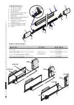
2
1
3
Ø 2,5
5
4
6
7
Ø 2,5
5
4
6
7
1
2
3
4
10
11
20 mm
8
9
p.
66
- M
an
ua
l c
od
e
FA
017
53
-E
N
FA
017
53
-E
N
- 0
1/
20
22 - © C
am
e S
.p
.A
. T
he c
on
te
nt
s o
f t
hi
s m
an
ua
l m
ay b
e c
ha
ng
ed a
t a
ny t
im
e w
ith
ou
t p
rio
r n
ot
ic
e.
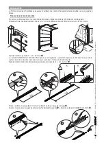
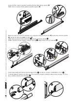
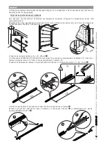
Fastening the sensitive safety-edge
Set up a Ø 10-mm corrugated connection tube
.
Place the braces at equal distances from the center, mark and drill the fastening holes
. Fasten the braces using Ø 4-mm
dowels and screws
.
If necessary (for example, with metal structures), use washer head self tapping Ø 3.9-mm screws.
Drill the back of the aluminum rail and set up the passing of the electrical cable
. Items: DFWN1500/1700/2000/2500
already have pre-drilled holes.
Use a probe to help the cable along the rail
.
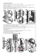
Place the sensitive-safety edge onto the braces (with the micro-switch holding mechanism facing up), drill on either side of
the rail using a Ø 2.5 mm bit
and fasten it using the UNI 6954 Ø 2.9x13 screws.
.
Make the electrical connections depending on the type of system (see electrical connections).
Adjust the tautness of the cable by turning the grub-screw on the micro-switch housing mechanism
and check whether
the micro-switch is works correctly: it should activate after maximum 20 mm of deformation
.
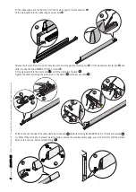
PROPER OPERATION:
- initial position
;
- micro-switch activation point (20 mm from the initial position), response time = 0.2 seconds
;
- maximum crushing position = 45 mm from the initial position
;
- initial position restoring time = 2 seconds
.
Fasten the mechanism using a screw
.
Fit the end cap and fasten it using UNI6954 Ø 3.9x13 screws and washers
11
.

