background image

Руково

дство 

FA01177-RU

 - 05/2018 - © CAME S.p.A. - Со

держание данног

о руково

дства може

т быть изменено в любое время без пре

дварит

ельног

о уве

домления.

 - Перево

д оригинальных инструкций

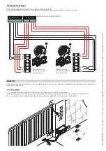
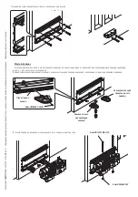
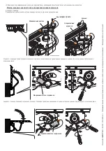
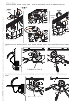
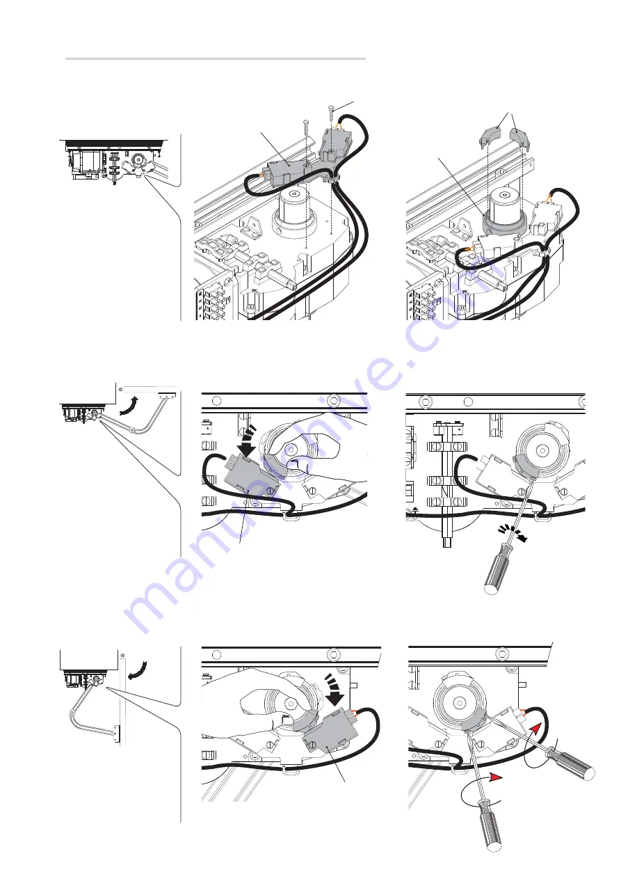
Откройте до конца створку ворот и вращайте другой кулачок по часовой стрелке до тех пор, пока не сработает микровыключатель 

открывания. Закрепите кулачок с помощью винтов.

Полностью закройте створку и вращайте кулачок против часовой стрелки до срабатывания микровыключателя закрывания. Зафиксируйте 

кулачок с помощью винтов. 

Микровыключа-

тель открывания

Микровыключатель закрывания

Концевой выключатель

Кулачки

Направляющая 

кулачков

⚠ 

Внимание: если механические упоры не предусмотрены, необходимо обязательно установить концевые выключатели.

Винт UNI6957 Ø2,9X19

Монтаж концевых выключателей и определение крайних положений

Для левого привода:

Прикрепите концевые выключатели к приводу и вставьте кулачки в направляющие.

Summary of Contents for FE40230

Page 1: ...FE40230 FE40230V IT Italiano EN English FR Français RU Русский FA01177M04 Automazione per cancelli a battente MANUALE DI INSTALLAZIONE ...

Page 2: ...novra del cancello Tenete fuori dalla loro portata i dispositivi di comando a distanza tra smettitori o qualsiasi altro dispositivo di comando per evitare che l automazione possa essere azionata involontariamente L apparecchio non è destinato a essere usato da persone bambini compresi le cui capacità fisiche sensoriali o mentali siano ridotte oppure con mancanza di esperienza o di conoscenza a men...

Page 3: ...ta m 2 5 2 1 5 Peso anta kg 300 500 550 Packing list 1 n 1 Motoriduttore 2 n 1 Staffa pilastro 3 n 1 Staffa cancello 4 n 1 Coperchio 5 n 1 Coperchio laterale destro 6 n 1 Coperchio laterale sinistro 7 n 1 Manuale d installazione 8 n 1 Braccio di trasmissione 9 n 1 Braccio condotto 10 n 1 Vite UNI5933 M6x20 11 n 1 Vite UNI5739 M8x16 12 n 2 Viti UNI5931 M8x120 13 n 4 Viti UNI6954 3 9x16 14 n 1 Vite ...

Page 4: ...Braccio telescopico dritto OPZIONALE FERNI BSX FERNI BDX Dati tecnici Tipo FE40230 FE40230V Grado di protezione IP 44 44 Alimentazione V 50 60 Hz 230 AC 230 AC Alimentazione motore V 50 60 Hz 230 AC 230 AC Assorbimento A 1 2 max 1 3 max Potenza W 140 150 Coppia Nm 540 max 320 max Tempo di apertura a 90 s 34 18 Intermittenza Lavoro 30 30 Temperatura di esercizio C 20 55 20 55 Termoprotezione motore...

Page 5: ... delle istruzioni originali Dimensioni mm Impianto tipo 1 Motoriduttore 2 Quadro comando 3 Scatola di derivazione 4 Antenna 5 Lampeggiatore 6 Selettore 7 Fotocellule 8 Pozzetto di derivazione 9 Elettroserratura 10 Battute di arresto meccanico 11 Colonnina per fotocellule IManuale FA01177 IT 05 2018 CAME S p A I contenuti del manuale sono da ritenersi suscettibili di modifica in qualsiasi momento s...

Page 6: ...ale fa fede la documentazione allegata ai prodotti stessi Tipi di cavi e spessori minimi INDICAZIONI GENERALI PER L INSTALLAZIONE L installazione deve essere effettuata da personale qualificato ed esperto e nel pieno rispetto delle normative vigenti Verifiche preliminari Prima di procedere all installazione è necessario Prevedere adeguato dispositivo di disconnesione onnipolare con distanza maggio...

Page 7: ...provenienti dal pozzetto di derivazione N B il numero di tubi dipende dal tipo di impianto e dagli accessori previsti Fissaggio delle staffe Nota i disegni si riferiscono all installazione del motoriduttore sinistro L installazione del motoriduttore destro è simmetrica Determinare il punto di fissaggio della staffa cancello e ricavare il punto di fissaggio della staffa pilastro rispettando le quot...

Page 8: ...gli inserti adeguati per la tenuta delle staffe Nota le illustrazioni sono indicative spetta all installatore scegliere la soluzione più adatta a seconda del tipo e spessore dell anta Segnare i punti di fissaggio della staffa pilastro e della staffa cancello rispettando le quote riportate nel disegno IManuale FA01177 IT 05 2018 CAME S p A I contenuti del manuale sono da ritenersi suscettibili di m...

Page 9: ...nella staffa e fissarlo con viti e dadi Dado UNI 5588 M8 Vite UNI 5931 M8x120 Fissaggio del motoriduttore Inserire i tegoli laterali nelle sedi di innesto della staffa pilastro Uno serve per il passaggio dei cavi l altro per il passaggio del braccio motoriduttore N B prima di inserire il tegolo per il passaggio dei cavi montare un pressacavo adeguato ai cavi da utilizzare Vite UNI 6954 2 9x9 5 IMa...

Page 10: ... Fissare il braccio condotto al braccio di trasmissione con la vite e la rondella Dado UNI 7774 M12 Vite UNI 5933 M6x20 Rondella Vite UNI 5739 M8x16 Rondella Vite UNI 5737 M12x50 Fissaggio dei bracci di trasmissione Inserire il braccio di trasmissione con la boccola nell albero motore e fissarlo con la rondella e la vite Boccola IManuale FA01177 IT 05 2018 CAME S p A I contenuti del manuale sono d...

Page 11: ...so antiorario fino all attivazione del micro di chiusura Fissare la camma con le viti Micro di apertura Micro di chiusura Finecorsa Camme Guida camme Attenzione se non ci sono le battute d arresto è obbligatorio fissare i finecorsa Vite UNI6957 Ø2 9X19 Fissaggio dei finecorsa e determinazione dei punti di finecorsa Per motoriduttore sinistro Fissare il finecorsa al motoriduttore e inserire le camm...

Page 12: ...Micro di apertura Micro di chiusura Finecorsa Aprire completamente l anta e ruotare l altra camma in senso antiorario fino all attivazione del micro di apertura Fissare la camma con le viti Chiudere completamente l anta e ruotare la camma in senso orario fino all attivazione del micro di chiusura Fissare la camma con le viti Camme Guida Vite UNI6957 Ø2 9X19 IManuale FA01177 IT 05 2018 CAME S p A I...

Page 13: ... azione ritardata in apertura Motoriduttore 230 V AC ad azione ritardata in chiusura COLLEGAMENTI ELETTRICI Morsettiera quadro comando 002ZM3E Foro per l astina di sblocco del motoriduttore sinistro Foro per l astina di sblocco del motoriduttore destro Ø12 mm OPERAZIONI FINALI Fissaggio dei coperchi A collegamenti e regolazioni effettuate forare il coperchio sul punto contrassegnato in alto per il...

Page 14: ...il coperchio Posizionare i coperchi laterali sui lati del coperchio centrale Fissare i coperchi laterali sulla staffa pilastro usando due viti per lato e una sulla parte alta Vite speciale M4x20 Vite UNI 6954 3 9x16 Fissaggio delle manopole di sblocco Inserire la manopola sull astina di sblocco e fissarla con la rondella e la vite IManuale FA01177 IT 05 2018 CAME S p A I contenuti del manuale sono...

Page 15: ...e standard Fissaggio delle staffe Nota i disegni si riferiscono all installazione del motoriduttore sinistro L installazione del motoriduttore destro è simmetrica Determinare il punto di fissaggio della staffa cancello e ricavare il punto di fissaggio della staffa pilastro rispettando le quote riportate nei disegni e nella tabella Staffa cancello Staffa pilastro Dimensioni applicazione Apertura an...

Page 16: ... senso orario fino all attivazione del micro di chiusura Fissare la camma con le viti Micro di apertura Micro di chiusura Finecorsa Camme Guida camme Attenzione se non ci sono le battute d arresto è obbligatorio fissare i finecorsa Vite UNI6957 Ø2 9X19 Fissaggio dei finecorsa e determinazione dei punti di finecorsa Per motoriduttore sinistro Fissare il finecorsa al motoriduttore e inserire le camm...

Page 17: ...Finecorsa Camme Guida Vite UNI6957 Ø2 9X19 Micro di apertura Micro di chiusura Aprire completamente l anta e ruotare la camma in senso orario fino all attivazione del micro di apertura Fissare la camma con le viti Chiudere completamente l anta e ruotare l altra camma in senso antiorario fino all attivazione del micro di chiusura Fissare la camma con le viti IManuale FA01177 IT 05 2018 CAME S p A I...

Page 18: ...menti elettrici MANUTENZIONE Prima di qualsiasi operazione di manutenzione togliere la tensione per evitare possibili situazioni di pericolo causate da accidentali movimentazioni dell automazione Manutenzione periodica È consigliabile un controllo periodico alla lubrificazione e all allentamento delle viti di fissaggio dell automazione Nel caso di vibrazioni anomale e cigolii lubrificare i punti d...

Page 19: ..._____________________ _________________________________________________________________________________________________ Timbro installatore Nome operatore Data intervento Firma tecnico Firma committente Intervento effettuato ____________________________________________________________________________________ __________________________________________________________________________________________...

Page 20: ...he batterie dei trasmettitori etc possono invece contenere sostanze inquinanti Vanno quindi rimossi e consegnati a ditte autorizzate al recupero e allo smaltimento degli stessi Prima di procedere è sempre opportuno verificare le normative specifiche vigenti nel luogo di smaltimento NON DISPERDERE NELL AMBIENTE PROBLEMA POSSIBILI CAUSE VERIFICHE E RIMEDI Il cancello non si apre e non si chiude Manc...

Page 21: ...FE40230 FE40230V EN English FA01177 EN Operator for swing gates INSTALLATION MANUAL ...

Page 22: ...here are no obstacles in the area of operation of the operator Do not allow children to play with the fixed command devices or in the gate s area of operation Keep any remote control devices i e transmitters or any control devices away from children as well to prevent the operator from being activated accidentally The operator is not designed to be used by persons including children whose physical ...

Page 23: ...500 600 800 With straight arm OPTIONAL and max leaf opening to 90 Type FE40230 FE40230V Gate leaf width m 2 5 2 1 5 Gate leaf weight kg 300 500 550 Packing list 1 1 x gearmotor 2 1 x pillar bracket 3 1 x gate bracket 4 1 x cover 5 1 x right side cover 6 1 x left side cover 7 1 x installation manual 8 1 x transmission arm 9 1 x driven arm 10 1 x UNI5933 M6x20 screw 11 1 x UNI5739 M8x16 screw 12 2 x...

Page 24: ...sion arm 8 Driven arm 9 Gate bracket 10 Release handle 11 OPTIONALstraighttelescopicarm FERNI BSX FERNI BDX Technical data Type FE40230 FE40230V Protection rating IP 44 44 Power supply V 50 60 Hz 230 AC 230 AC Motor power supply V 50 60 Hz 230 AC 230 AC Power draw A 1 2 max 1 3 max Power W 140 150 Torque Nm 540 max 320 max Opening time to 90 sec 34 18 Duty cycle 30 30 Operating temperature C 20 55...

Page 25: ...S p A The contents of this manual may change at any time and without notice Translated original instructions Dimensions mm Example of a system 1 Gearmotor 2 Control panel 3 Junction box 4 Antenna 5 Flashing light 6 Selector 7 Photocells 8 Inspection chamber 9 Electric lock 10 Mechanical stops 11 Photocell column ...

Page 26: ... When connecting products that are not specified in this manual please refer to the documentation provided with said products Types of cables and minimum thicknesses GENERAL INSTALLATION INSTRUCTIONS Installation must be carried out by qualified and experienced personnel in compliance with applicable regulations Preliminary checks Before starting installation Provide a suitable single pole disconn...

Page 27: ...uitable solution Installing corrugated tubes Set up corrugated tubes for the connections coming from the junction box N B the number of tubes depends on the type of system installed and any accessories Securing the brackets N B the drawings refer to installation of the left hand gearmotor The installation of the right hand gearmotor is symmetrical Determine the fixing point for the gate bracket an...

Page 28: ...nstructions Drill the marked points Insert the anchors or use suitable inserts for holding the brackets N B the illustrations are mere examples it is up to the installer to choose the most suitable solution depending on leaf type and thickness Mark the fixing points on the pillar bracket and gate bracket respecting the values shown in the drawing ...

Page 29: ...ansmission arm passage Slot Insert the gearmotor into the bracket and secure it with screws and nuts UNI 5588 M8 nut UNI 5931 M8x120 screw Securing the gearmotor Insert the side panels in the pillar bracket slots One is used for passing through the cables the other for passing through the gearmotor arm N B before inserting the panel for passing through the cables assemble a cable gland suitable fo...

Page 30: ...nd secure the drive arm to the gate bracket with the screw and nut Secure the drive arm to the transmission arm using the screw and washer UNI 7774 M12 nut UNI 5933 M6x20 screw Washer UNI 5739 M8x16 screw Washer UNI 5737 M12x50 screw Securing the transmission arms Insert the transmission arm with the bushing in the motor shaft and secure it with the washer and screw Bushing ...

Page 31: ...the cam with the screws Close the leaf fully and turn the cam anti clockwise until the closing microswitch is activated Secure the cam with the screws Opening mi croswitch Closing microswitch End run Cams Cam guide Caution if there are no end stops end runs must be fitted UNI6957 Ø2 9X19 screw Securing the end runs and determining the end run points For left hand gearmotor Secure the end run to th...

Page 32: ...e gearmotor invert the microswitch cables and insert the cams on the guide Opening mi croswitch Closing microswitch End run Fully open the leaf and turn the other cam anti clockwise until the opening microswitch is activated Secure the cam with the screws Close the leaf fully and turn the cam clockwise until the closing microswitch is activated Secure the cam with the screws Cams Rail UNI6957 Ø2 9...

Page 33: ...he technical documentation for the control panel 230 VAC gearmotor with delaying opening action 230 VAC gearmotor with delaying closing action ELECTRICAL CONNECTIONS 002ZM3E control panel terminal block Hole for the left hand motor release rod Hole for the right hand motor release rod Ø12 mm FINAL OPERATIONS Securing the covers When the connections and adjustments have been made drill the cover at...

Page 34: ...UNI 6954 3 9x9 5 screw Connect the earth wire to the motor Put on the cover Place the side covers on the sides of the middle cover Secure the side covers on the pillar bracket using two screws on each side and one on the top M4x20 special screw UNI 6954 3 9x16 screw Securing the release knobs Insert the knob onto the release rod and secure it using the washer and the screw ...

Page 35: ...fer to installation of the left hand gearmotor The installation of the right hand gearmotor is symmetrical Determine the fixing point for the gate bracket and calculate the fixing point of the pillar bracket respecting the values shown in the drawings and table Gate bracket Pillar bracket INSTALLING AND CONNECTIONS FOR OUTWARD OPENINGS Below are the only procedures that vary compared to standard i...

Page 36: ...uns must be fitted UNI6957 Ø2 9X19 screw Securing the end runs and determining the end run points For left hand gearmotor Secure the end run to the gearmotor and insert the cams on the guide Open the leaf fully and turn the cam anti clockwise until the opening microswitch is activated Secure the cam with the screws Close the leaf fully and turn the other cam clockwise until the closing microswitch...

Page 37: ...e gearmotor invert the microswitch cables and insert the cams on the guide End run Cams Rail UNI6957 Ø2 9X19 screw Opening microswitch Closing microswitch Open the leaf fully and turn the cam clockwise until the opening microswitch is activated Secure the cam with the screws Close the leaf fully and turn the other cam anti clockwise until the closing microswitch is activated Secure the cam with th...

Page 38: ...ent refer to the technical documentation for the control panel Electrical connections MAINTENANCE Before any maintenance disconnect power to prevent any possible dangerous situations that can be caused by accidental movement of the operator Periodic maintenance It is advisable to check lubrication periodically and check that the operator fixing screws are tight In the event of abnormal vibrations ...

Page 39: ...________________________________________ _________________________________________________________________________________________________ Installation technician stamp Operator name Date of intervention Technician signature Customer signature Intervention carried out __________________________________________________________________________________ ________________________________________________...

Page 40: ...ted sorted and sent to authorised centres Other components circuit boards transmitter batteries etc on the other hand may contain pollutants They should therefore be removed and handed over to companies authorised to recover and recycle them Before proceeding it is always advisable to check specific regulations in force in the place of disposal DISPOSE OF PROPERLY PROBLEM POSSIBLE CAUSES CHECKS AN...

Page 41: ...FE40230 FE40230V FR Français FA01177 FR Automatisme pour portails battants MANUEL D INSTALLATION ...

Page 42: ...e Ne pas permettre aux enfants de jouer avec les dis positifs de commande fixes ou de stationner dans la zone de manœuvre du portail Conserver hors de leur portée les dispositifs de commande à distance émetteurs ou tout autre dispositif de commande afin d éviter l actionnement involontaire de l automatisme L appareil n a pas été conçu pour être utilisé par des personnes y compris des enfants aux cap...

Page 43: ...antail kg 400 450 500 600 800 Avec bras droit EN OPTION et ouverture vantail max à 90 Type FE40230 FE40230V Largeur vantail m 2 5 2 1 5 Poids vantail kg 300 500 550 Liste du matériel 1 1 Motoréducteur 2 1 Étrier pilier 3 1 Étrier portail 4 1 Couvercle 5 1 Couvercle latéral droit 6 1 Couvercle latéral gauche 7 1 Manuel d installation 8 1 Bras de transmission 9 1 Bras mené 10 1 Vis UNI5933 M6x20 11 ...

Page 44: ...s de transmission 8 Bras mené 9 Étrier portail 10 Poignée de déblocage 11 BrastélescopiquedroitENOPTION FERNI BSX FERNI BDX Données techniques Type FE40230 FE40230V Degré de protection IP 44 44 Alimentation V 50 60 Hz 230 AC 230 AC Alimentation moteur V 50 60 Hz 230 AC 230 AC Absorption A 1 2 max 1 3 max Puissance W 140 150 Couple Nm 540 max 320 max Temps d ouverture à 90 s 34 18 Intermittence Fon...

Page 45: ... subir des modifications à tout moment et sans aucun préavis Traduction des instructions originales Dimensions mm Installation type 1 Motoréducteur 2 Tableau de commande 3 Boîtier de dérivation 4 Antenne 5 Feu clignotant 6 Sélecteur 7 Photocellules 8 Boîtier de dérivation 9 Serrure de verrouillage électrique 10 Butées mécaniques 11 Colonne pour photocellules ...

Page 46: ...e produits non indiqués dans ce manuel considérer comme valable la documentation jointe à ces derniers Types de câbles et épaisseurs minimum INSTRUCTIONS GÉNÉRALES POUR L INSTALLATION L installation doit être effectuée par du personnel qualifié et dans le plein respect des normes en vigueur Contrôles préliminaires Avant de procéder à l installation il faut Prévoir un dispositif de déconnexion omni...

Page 47: ...ution la plus indiquée Pose des tuyaux annelés Prévoir les tuyaux annelés nécessaires pour les raccordements issus du boîtier de dérivation N B le nombre de tuyaux dépend du type d installation et des accessoires prévus Fixation des étriers Remarque les dessins se réfèrent à l installation du motoréducteur gauche L installation du motoréducteur droit est symétrique Identifier le point de fixation ...

Page 48: ...x endroits signalés Introduire les chevilles ou utiliser des éléments adéquats pour la fixation des étriers Remarque les illustrations ne sont fournies qu à titre indicatif et c est l installateur qui doit choisir la solution la plus appropriée selon le type et l épaisseur du vantail Noter les points de fixation de l étrier pilier et de l étrier portail en respectant les dimensions indiquées sur l...

Page 49: ...u bras du motoréducteur Point de fixation Introduire le motoréducteur dans l étrier et le fixer à l aide des vis et des écrous Écrou UNI 5588 M8 Vis UNI 5931 M8x120 Fixation du motoréducteur Introduire les plaques latérales dans les points de fixation de l étrier pilier Une de ces plaques a été prévue pour le passage des câbles et l autre pour le passage du bras du motoréducteur N B avant d appliq...

Page 50: ...gure et fixer le bras mené à l étrier portail à l aide de la vis et de l écrou Fixer le bras mené au bras de transmission à l aide de la vis et de la rondelle Écrou UNI 7774 M12 Vis UNI 5933 M6x20 Rondelle Vis UNI 5739 M8x16 Rondelle Vis UNI 5737 M12x50 Fixation des bras de transmission Introduire le bras de transmission avec la douille dans l arbre moteur et le fixer à l aide de la rondelle et de...

Page 51: ... complètement le vantail et tourner la came dans le sens contraire à celui des aiguilles d une montre jusqu à activation du minirupteur de fermeture Fixer la came à l aide des vis Minirupteur d ouver ture Minirupteur de fermeture Fin de course Cames Guide cames Attention la fixation des fins de course est obligatoire en cas d absence des butées d arrêt Vis UNI6957 Ø2 9X19 Fixation des fins de cour...

Page 52: ...rupteurs et introduire les cames dans le guide Minirupteur d ouver ture Minirupteur de fermeture Fin de course Ouvrir complètement le vantail et tourner l autre came dans le sens contraire à celui des aiguilles d une montre jusqu à activation du minirupteur d ouverture Fixer la came à l aide des vis Fermer complètement le vantail et tourner la came dans le sens des aiguilles d une montre jusqu à a...

Page 53: ...r la documentation technique de l armoire de commande Motoréducteur 230 V AC à action retardée en phase d ouverture Motoréducteur 230 V AC à action retardée en phase de fermeture BRANCHEMENTS ÉLECTRIQUES Barrette armoire de commande 002ZM3E Trou pour la tige de déblo cage du motoréducteur gauche Trou pour la tige de déblo cage du motoréducteur droit Ø12 mm OPÉRATIONS FINALES Fixation des couvercle...

Page 54: ...Connecter le câble de mise à la terre au motoréducteur Fixer le couvercle Positionner les couvercles latéraux sur les côtés du couvercle central Fixer les couvercles latéraux sur l étrier pilier à l aide de deux vis pour chaque côté et d une vis sur la partie supérieure Vis spéciale M4x20 Vis UNI 6954 3 9x16 Fixation des poignées de déblocage Appliquer la poignée sur la tige de déblocage et la fix...

Page 55: ...rent à l installation du motoréducteur gauche L installation du motoréducteur droit est symétrique Identifier le point de fixation de l étrier portail et établir celui de l étrier pilier en respectant les dimensions indiquées sur les dessins et dans le tableau Étrier portail Étrier pilier INSTALLATION ET CONNEXIONS POUR UNE OUVERTURE VERS L EXTÉRIEUR Les opérations décrites ci après sont les seule...

Page 56: ... des butées d arrêt Vis UNI6957 Ø2 9X19 Fixation des fins de course et détermination des points de fin de course Pour motoréducteur gauche Fixer la buté de fin de course au motoréducteur et introduire les cames dans le guide Ouvrir complètement le vantail et tourner la came en sens anti horaire jusqu à activation du micro interrupteur d ouverture Fixer la came à l aide des vis Fermer complètement ...

Page 57: ...rser les câbles des minirupteurs et introduire les cames dans le guide Fin de course Cames Guide Vis UNI6957 Ø2 9X19 Minirupteur d ouverture Minirupteur de fermeture Ouvrir complètement le vantail et tourner la came en sens horaire jusqu à activation du micro interrupteur d ouverture Fixer la came à l aide des vis Fermer complètement le vantail et tourner l autre came en sens anti horaire jusqu à ...

Page 58: ...es réglages consulter la documentation technique de l armoire de commande Branchements électriques ENTRETIEN Avant toute autre opération d entretien il est conseillé de mettre hors tension pour éviter toute situation de danger provoquée par des déplacements accidentels de l automatisme Entretien périodique Il est conseillé de contrôler régulièrement la lubrification et le serrage des vis de fixati...

Page 59: ...__________________________________________________________________________________________ _________________________________________________________________________________________________ Timbre installateur Nom opérateur Date intervention Signature technicien Signature client Intervention effectuée ___________________________________________________________________________________ ______________...

Page 60: ...te et de l élimination différenciées auprès des centres autorisés D autres composants cartes électroniques batteries des émetteurs etc peuvent par contre contenir des substances polluantes Il faut donc les désinstaller et les remettre aux entreprises autorisées à les récupérer et à les éliminer Avant d effectuer ces opérations il est toujours recommandé de vérifier les normes spécifiques en vigueu...

Page 61: ...FE40230 FE40230V RU Pусский FA01177 RU Привод для распашных ворот РУКОВОДСТВО ПО УСТАНОВКЕ ...

Page 62: ...ободным и чистым участок движения ворот Сле дите за тем чтобы в зоне действия фотоэлементов не было растительности и препятствий для движения ворот Не позволяйте детям играть с перенос ными или фиксированными командными устройствами или находиться в зоне движения ворот Храните брелоки передатчики и другие устройства в недоступном для детей месте во избежание случайного запуска системы Устройство н...

Page 63: ...ящимрычагом ОПЦИЯ имакс угломоткрываниястворкидо90 Модель FE40230 FE40230V Ширина створки м 2 5 2 1 5 Масса створки кг 300 500 550 Упаковочный лист 1 Привод 1 шт 2 Задний кронштейн 1 шт 3 Передний кронштейн 1 шт 4 Крышка 1 шт 5 Правая боковая крышка 1 шт 6 Левая боковая крышка 1 шт 7 Инструкция по монтажу 1 шт 8 Рычаг передачи 1 шт 9 Тяга 1 шт 10 Винт UNI 5933 M6x20 1 шт 11 Винт UNI5739 M8x16 1 шт...

Page 64: ...яга 9 Передний кронштейн 10 Ручка разблокировки 11 Скользящий телескопический рычаг ОПЦИЯ FERNI BSX FERNI BDX Технические характеристики Модель FE40230 FE40230V Класс защиты IP 44 44 Электропитание В 50 60 Гц 230 230 Напряжение питания двигателя В 50 60 Гц 230 230 Потребляемый ток А 1 2 макс 1 3 макс Мощность Вт 140 150 Крутящий момент Нм 540 макс 320 макс Время открывания на 90 с 34 18 Интенсивно...

Page 65: ...жет быть изменено в любое время без предварительного уведомления Перевод оригинальных инструкций Габаритные размеры мм Пример типовой установки 1 Привод 2 Блок управления 3 Разветвительная коробка 4 Антенна 5 Cигнальная лампа 6 Кодонаборная клавиатура 7 Фотоэлементы 8 Разветвительный колодец 9 Электрозамок 10 Механические упоры 11 Стойка под фотоэлементы ...

Page 66: ...ческих расстояний При подключении устройств не рассматриваемых в данной инструкции следует руководствоваться технической документацией на соответствующее изделие Тип и сечение кабелей ОБЩИЕ ИНСТРУКЦИИ ПО МОНТАЖУ Монтаж должен производиться квалифицированным персоналом в полном соответствии с требованиями действующих норм безопасности Предварительные проверки Перед тем как приступить к монтажным ра...

Page 67: ...н осуществляться установщиком на месте Прокладка гофрированных труб Проложите трубы и гофрошланги для проводов и кабелей от разветвительного колодца Важное примечание требуемое количество каналов зависит от типа системы и подключаемых аксессуаров Монтаж кронштейнов Примечание рисунки иллюстрируют схему монтажа левого привода Монтаж правого привода выполняется симметрично Определите место крепления...

Page 68: ...ций Просверлите отверстия в обозначенных местах Вставьте дюбели или используйте вкладыши подходящие для крепежа пластин Примечание все рисунки носят исключительно иллюстративный характер поэтому выбор наиболее подходящего решения осуществляется установщиком на месте с учетом типа и толщины створки Обозначьте места крепления переднего и заднего кронштейнов соблюдая указанные расстояния ...

Page 69: ...ставка для пропуска рычага привода Отверстие кре пления Вставьте привод в кронштейн и зафиксируйте его с помощью винтов и гаек Гайка UNI 5588 M8 Винт UNI 5931 M8x120 Монтаж привода Установите боковые вставки в отверстия крепления заднего кронштейна Одна из боковых вставок необходима для прокладки кабелей другая для пропуска рычага привода Важное примечание прежде чем установить боковую вставку для...

Page 70: ...Разблокируйте привод см рисунок и прикрепите тягу к переднему кронштейну посредством винта и гайки Прикрепите тягу к рычагу передачи с помощью винта и шайбы Гайка UNI 7774 M12 Винт UNI 5933 M6x20 Шайба Винт UNI 5739 M8x16 Шайба Винт UNI 5737 M12x50 Крепление рычагов передачи Вставьте рычаг передачи с втулкой в приводной вал и прикрепите его с помощью винта и шайбы Втулка ...

Page 71: ... Полностью закройте створку и вращайте кулачок против часовой стрелки до срабатывания микровыключателя закрывания Зафиксируйте кулачок с помощью винтов Микровыключа тель открывания Микровыключатель закрывания Концевой выключатель Кулачки Направляющая кулачков Внимание если механические упоры не предусмотрены необходимо обязательно установить концевые выключатели Винт UNI6957 Ø2 9X19 Монтаж концевы...

Page 72: ...елей местами и вставьте кулачки в направляющую Микровыключа тель открывания Микровыключатель закрывания Концевой выключа тель Откройте до конца створку ворот и вращайте другой кулачок против часовой стрелки до тех пор пока не сработает микровыключатель открывания Закрепите кулачок с помощью винтов Полностью закройте створку и вращайте кулачок по часовой стрелке до срабатывания микровыключателя зак...

Page 73: ...ировках системы ознакомьтесь с технической документацией прилагаемой к блоку управления Привод 230 В с замедленным открыванием Привод 230 В с замедленным закрыванием ЭЛЕКТРИЧЕСКИЕ ПОДКЛЮЧЕНИЯ Колодка блока управления 002ZM3E Отверстие для рычага разблокировки левого привода Отверстие для рычага разблокировки правого привода Ø12 мм ЗАКЛЮЧИТЕЛЬНЫЕ РАБОТЫ Монтаж и крепление крышек После выполнения не...

Page 74: ...92 4 3x9 Винт UNI 6954 3 9x9 5 Подключите провод заземления к приводу Вставьте крышку Установите боковые крышки по краям центральной крышки Прикрепите боковые крышки к заднему кронштейну используя два винта с каждой стороны и один в верхней части Специальный винт M4x20 Винт UNI 6954 3 9x16 Крепление ручек разблокировки Вставьте ручку в рычаг разблокировки и зафиксируйте ее с помощью шайбы и винта ...

Page 75: ...ронштейнов Примечание рисунки иллюстрируют схему монтажа левого привода Монтаж правого привода выполняется симметрично Определите место крепления переднего кронштейна и рассчитайте место крепления заднего кронштейна соблюдая расстояния указанные в таблице Передний кронштейн Задний кронштейн МОНТАЖ ПРИВОДА С ОТКРЫВАНИЕМ НАРУЖУ Ниже приведены только те работы которые отличаются от стандартной процед...

Page 76: ...смотрены необходимо обязательно установить концевые выключатели Винт UNI6957 Ø2 9X19 Монтаж концевых выключателей и определение крайних положений Для левого привода Прикрепите концевые выключатели к приводу и вставьте кулачки в направляющие Откройте створку до упора и поверните кулачок против часовой стрелки до срабатывания концевого выключателя открывания Зафиксируйте кулачок винтами Закройте ств...

Page 77: ...вода микровыключателей местами и вставьте кулачки в направляющую Концевой выключа тель Кулачки Направля ющая Винт UNI6957 Ø2 9X19 Микровыключатель открывания Микровыключатель закрывания Откройте створку до упора и поверните кулачок по часовой стрелке до срабатывания концевого выключателя открывания Зафиксируйте кулачок винтами Закройте створку и поверните кулачок против часовой стрелки до срабатыв...

Page 78: ...емы ознакомьтесь с технической документацией прилагаемой к блоку управления Электрические подключения ТЕХНИЧЕСКОЕ ОБСЛУЖИВАНИЕ Перед выполнением работ по техническому обслуживанию отключите питание во избежание возникновения опасных ситуаций вызванных непроизвольным движением ворот Периодическое техническое обслуживание Кроме того рекомендуется периодически проверять состояние смазки и надежность ...

Page 79: ..._____________________________ _________________________________________________________________________________________________ _________________________________________________________________________________________________ Место печати Компания Дата проведения работ Подпись установщика Подпись заказчика Выполненные работы _________________________________________________________________________...

Page 80: ... Они могут быть переработаны специализированными компаниями Другие компоненты электрические монтажные платы элементы питания дистанционного управления и т д могут содержать опасные отходы Они должны передаваться компаниям имеющим лицензию на их переработку НЕ ЗАГРЯЗНЯЙТЕ ОКРУЖАЮЩУЮ СРЕДУ НЕИСПРАВНОСТЬ ВОЗМОЖНАЯ ПРИЧИНА СПОСОБ УСТРАНЕНИЯ Ворота не открываются и не закрываются Нет напряжения питания...

Reviews: