FA00150-EN v.7 - 06/2017
12
CAME S.p.A.
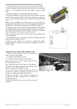
5.4 Secure by front hooking the transmission unit on the drive unit profile,
place it to maximum A (as described in Chapter 4), and secure it with the
screws (Note: if there is space, it’s better to reduce measure A few
centimetres).
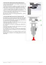
5.5 Insert the carriages in front of the drive unit profile, and adjust the upper
wheel, so you do not let them get out of the rail profile [104] In case of 2-
leaves automation, also add the carriages for the left leaf.
N.B. The carriage should be positioned as shown in Chapter 4.
Note: if the sliding door has a break-out system, it is necessary to add the
second upper wheel on each carriage, as indicated in the figure, to avoid
that very strong pushing of leaf causes the output of the carriage from the
rail profile.
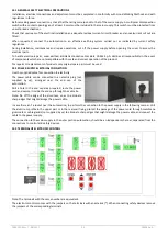
5.6 Insert the two front brackets mechanical stop near the end caps, and
secure with the screws. In the case of 2-leaves automation, add a
mechanical stop bracket to the center.
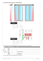
5.7 Insert the belt in the pulley motor drive unit, slide it and pass it around
the transmission unit and fix to carriage with the proper springs (see the belt
attack position, as shown in Chapter 4).


