FA00150-EN v.7 - 06/2017
16
CAME S.p.A.
7. INSTALLATION OF LOCKING DEVICE 001FLA-03
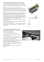
- Fix by front hooking, the locking device on the drive unit profile , place in C Measure (as indicated in Chapter 4), and secure
with screws.
- Fix the hook bracket on the carriage in relation of the door type, as indicated in Chapter 4:
Note: if the hook bracket touches the mechanical stop bracket on FLUO-SLB automation, use the included spacer.
- Manually move the door in closed position and adjust the bracket and/or locking device position to get the proper
attachment of the locking device.
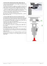
- Connect the locking device to the connector LK of electronic control using the included cable (the excess may be
shortened). Observe the color of the wires (red to red and black to black).
- Switch the unlock rope through present hole on the left end caps, until you reach the locking device. Switch the rope
through the spring and lock, making a lap around the bracket. With the door in closed position and locked, check manually
pulling the unlock rope, manually open the door.
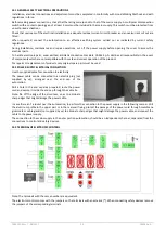
- In case you need to move the unlock rope through the right end caps, proceed as follows:
- Unscrew the 4 lower screws [a] of the lock,
- Rotate the lock so that the spring [b] is on the left,
- Rescrew the 4 lower screws [a] of the lock.
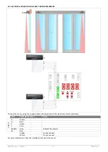
Note: pulling the unlock rope the doors are unlocked, also in the absence of electricity, and remain unlocked until is not
restored electrical operation.


