FA00150-EN v.7 - 06/2017
17
CAME S.p.A.
8. INSTALLATION OF BATTERY POWER DEVICE 001FLA-01, 001FLA-02
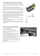
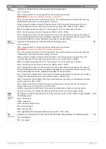
- Fix by front hooking, the battery power device on the drive unit profile.
- Connect the battery power device to the BAT connector of the electronic
control, or of the Emergency electronic card [CB02], using the supplied
cable.
- Ensure that the battery is connected to the electronic board.
- Connect the automation to the power supply and wait at least 30 minutes
to let the battery recharge. Make sure that removing the power supply, the
door is working with battery power device, in mode choice using the BTMD
menu.
Note: to allow recharging, the battery power device must always be
connected to the electronic control. In case of long periods of inactivity of
the automatic door, disconnect the battery from the electronic board.
- If desired, you can connect a LED to signal the presence of the battery
(not supplied) between the terminals [+] and [LD] as shown in the figure. In
the presence of mains power, the LED makes a blink every 10 seconds,
while in the absence of mains power, the LED remains lit.
Note: it’s possible to position the LED on the right end caps, making a hole
on the suitable area.
- In the absence of mains power, battery operation is disabled when the
charge level of the battery is too low.
If desired, you can connect a N.O. contact to reactivate the battery
operation (example a key switch) between the terminals [+] and [KY ] as
shown in Figure.
9. INSTALLATION OF SUPPORT FOR SENSOR 001FLA-08
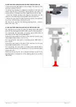
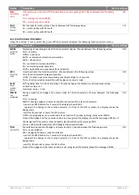
- Attach the opening and safety sensor to the fixing sensor,
using 2 of the 4 screws supplied:
- n. 2 screws 3,5x9,5 for Bircher sensors;
- n. 2 screws 3,5x6,5 for BEA, Optex, Hotron sensors.
Note: do not use the screws supplied with the sensor,
because they are too long.
If you use safety sensors, cut the extra part of the bracket.
- Switch the sensor cable through the hole in the bracket and
secure it to support itself through the strap.
- Fix by front hooking, the fixing sensor and the sensor on
the drive unit profile, and place it at the centre of the
doorway, or sideways at the opening of the doors.
- Check the operation of the magnetic coupling and
uncoupling of the sensor support, even in the presence of
the cover automation.
- Connect the sensors to the electronic control, as shown in
Chapter 12.


