FA00150-EN v.7 - 06/2017
21
CAME S.p.A.
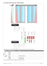
Terminals
Description
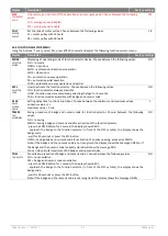
0 – 1
Output 12 Vdc for external powering accessories. The maximum absorption of 1 A corresponds to the
sum of all the terminals 1 (+12V).
1 – 3A
Contact N.O. opening A side (interior side).
1 – 3B
Contact N.O. opening B side (outer side).
1 – KO
Contact N.O. aperture priority, connect to devices accessible only by authorized personnel with keys or
codes.
1 – KC
Contact N.O. closing priority, connect to devices accessible only by authorized personnel with keys or
codes.
1 – 8A
Safety contact N.C. on doorway side A (interior side). When the door is closing, the opening of the
contact causes the reversal of the movement.
Note: connect safety devices with test (see terminal 41), and remove the jumper 41 - 8A.
1 – 8B
Safety contact N.C. on doorway side B (outer side). When the door is closing, the opening of the contact
causes the reversal of the movement.
Note: connect safety devices with test (see terminal 41), and remove the jumper 41 - 8A.
1 – 6A
Opening safety contact N.C. side A (left side). When the door is opening, the opening of the contact
causes the slowdown of the door in the last 500 mm (the safety function of the terminal 6 can be
changed using the advanced settings menu).
Note: connect safety devices with test (see terminal 41), and remove the jumper 41 - 6A.
1 – 6B
Opening safety contact N.C. side B (right side). When the door is opening, the opening of the contact
causes the slowdown of the door in the last 500 mm (the safety function of the terminal 6 can be
changed using the advanced settings menu).
Note: connect safety devices with test (see terminal 41), and remove the jumper 41 - 6A.
41
Output test (+12 V). Connect the safety devices with test (in accordance with EN 16005), as indicated in
the following chapters.
Note: in case of devices without test, connect the N.C. contact to terminals 41 - 8A or 41 - 8B, or 41 - 6A,
or 41 - 6B.
1 – G1
Input terminal provided for general use.
Using the ADV > STG1 menu you can choose a specific function to the G1 terminal.
1 – G2
0 – G2
Input terminal provided for general use.
Output terminal (12 Vdc, 20mA max) provided for general use.
Using the ADV > STG2 menu you can choose a specific function to the G2 terminal.
1 – S1
Contact N.C. limit-switch of the locking device.
1 – 29
Reset contact N.O. Closure and release the contact starts the learning operation of the door.
0 – 1 – H – L
Bus connection to the function selector.
SD
Standard admission for memory cards Micro SD. Allows saving the door settings and loading the firmware
updates.
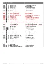
Terminals
Description
R1 – R0
Current input for the opening sensor for emergency exit side A, internal view of automation (remove the
jumper and the resistor of the terminals).
1 – EO
Contact N.C. of emergency opening. The opening of the contact causes the door to open (connect the
emergency opening device and remove the bridge 1 – EO).
Buttons
Description
OPEN
Open the door.
↑
Scroll the menu and increase of selected values.
↓
Scroll the menu and reduction of selected values.
ENTER
Button to select the menu and save the selected data.
ESC
Exit the menu.


