background image

- 15 -

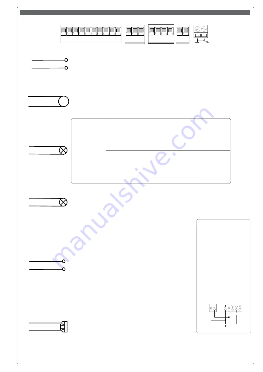
Alimentazione 230V (a.c.)
230V (a.c.) power supply
Alimentation 230V (c.a.)
Stromversorgung 230V Wechselstrom)
Alimentación 230V (a.c.)

Motore 24V(d.c.)
24V (d.c.) motor
Moteur 24V (c.c.)
Motor 24V (Gleichstrom)
Motor 24V (d.c.)

Uscita 24V in movimento (es.lampeggiatore - dip 3 OFF)
24V output in motion (e.g. flashing light - Pos. B Jumper)
Sortie 24V en mouvement (ex. branchement clignotant - Jumper  Pos. B)
Ausgang 24V in Bewegung (z.B. Blinker-Anschluß - Jumper Pos. B)
Salida de 24V en movimento (ej. lámpara intermitente - Jumper Pos. B)

Lampada spia 24V-3W max. "sbarra aperta"
24V -3W max. "bar-opened" signal lamp
Lampe-témoin 24V-3W max. "lisse ouverte"
Kontrollampe 24V-3W max. "Schranke offen"
Lámpara de señal 24V-3W max. "barra abierta"

 Alimentazione accessori  (max 40W):
 - 24V (a.c.) con alimentazione a 230V(a.c.)
 - 24V (d.c.) con alimentazione a  24V (d.c.)
Power supply accessories (max. 40W):
 24V (a.c.) with power supply at 230V (a.c.)
 24V (d.c.) with power supply at  24V (d.c.)
Alimentation accessories  (max 40W):
 - 24V (a.c.) avec alimentation à 230V(c.a.)
 - 24V (d.c.) avec alimentation a  24V (c.c.)
Stromversorgung Zubehör (max 40W):
 - 24V (Wechselstrom) bei Stromversorgung 230V(Wechselstrom)
 - 24V (Gleichstrom) bei Stromversorgung  24V (Gleichstrom)
Alimentación accesorios  (max 40W):
 - 24V (a.c.) con alimentación a 230V(a.c.)
 - 24V (d.c.) con alimentación a  24V (d.c.)

Pulsante stop (N.C.)
Pushbutton stop (N.C.)
Bouton-poussoir arrêt (N.F.)
Stop-Taste (N.C.)
Pulsador de stop (N.C.)

10

 E

L1

L2

N.B. Rispettare la polarità nel
collegamento delle fotocellu-
le (TX e RX).

N.B. When connecting the
photocells (TX and RX),
observe the correct
polarities.

N.B. Respecter la polarité lors
de la connexion des
photocellules (TX et RX).

Anmerkung: beim
Anschließen der Photozellen
(TX und RX) auf die Polung
achten.

N.B. Respetar la polaridad en
la conexión de las fotocélulas
(TX y RX).

10 11

RX

NO C NC

TX

10

11

M

N

10

 5

 1

 2

FA FC F PT

E +10-11 1 2

C1C5

7

3 5

INTERBLOCCO

M N

in movimento (es.lampeggiatore)

during movement (e.g. flashing light)

en mouvement (ex. clignotant)

während der Bewegungsphase (z.B. Blinker)

en movimiento (ej. lámpara intermitente)

Uscita 24V
24V output
Sortie 24V
Ausgang 24V
Salida de 24V

in movimento e in posizione di chiusura

during movement and in the closed position

en mouvement et en position de fermeture

während der Bewegungsphase und bei Schließstellung

en movimiento y en posición de cierre

DIP 3

OFF

DIP 3

ON

Collegamenti elettrici // 

Electrical connections // Branchements électriques // Elektrische anschlüsse // Conexions eléctricas

Summary of Contents for G 6000

Page 1: ...anti choc 7 Lampe de mouvement 8 Clignotant de mouvement 9 S lecteur cl 10 Batterie d urgence 11 Colonnette pour photocellule 12 Photocellule de s curit 13 Colonnette pour lecteur de carta magn tique...

Page 2: ...er l applicazione del lampeggiatore su armadio ACCESSORI OPZIONALI Models G6000 Barrier with non reversible 24 V d c gear motor case in galvanised steel with enamel finish control panel and internal d...

Page 3: ...pplication d une photocellule sur l armoire G0469 Support pour l application du clignotant sur l armoire ACCESSOIRES EN OPTION Modelle G6000 Schranke mit selbsthemmendem 24 V Gleichstrom Getriebemotor...

Page 4: ...sforescente para las barras G0462 Apoyo fijo para las barras G0463 Apoyo m vil para las barras G0465 Estante de aluminio barnizado blanco para las barras G0467 Articulaci n para G0601 G0468 Soporte pa...

Page 5: ...finition galvanis e Il permet un blocage rapide et s r de la lisse D Le d blocage du motor ducteur grace un cin matisme sp cial s effectue au moyen d une cl personnalis e E Moteur en courant continu...

Page 6: ...el equipo Regular el alineado vertical y horizontal del hasta actuando en el tope mec nico B y en la palanca de transmisi n C I GB F D E 1 Predisponer en funci n de las medidas del grupo una plataform...

Page 7: ...on B If the final configuration of your barrier requires a change in the position of the springs see illustrations unlock the gear motor and change the position of the springs do not throw away the sp...

Page 8: ...GB I F D E To balance the barrier rod precisely proceed as follows 1 Unlock the gear motor p 5 ref D 2 Loosen locknuts B on tension rods A 3 Manually adjust the springs to increase decrease their tens...

Page 9: ...della barriera Funzione slave nel caso di due motori abbinati vedi pag 22 Aumento dell azione frenante della sbarra Tipo di comando apre chiude solo apertura ENGLISH This control board is powered by...

Page 10: ...n d une sortie 24V pendant les phases de mouvement et en position de fermeture Fonctionnement slave en cas de deux moteurs associ s voir page 22 Augmentation de l action de freinage de la barri re DEU...

Page 11: ...Los dispositivos de mando son a baja tensi n 24V protegidos por fusible a 2A La potencia total de los accesorios a 24V no debe superar los 20W Seguridad Las fotoc lulas pueden estar conectadas y predi...

Page 12: ...keit 8 Code Speichertast 9 Schlie automatik Anzeige LED Funkcode 10 Steckverbinder Stromversorgung Motor 11 Steckverbinderf rBatterieladeger t Anschlu LB35 12 Steuerart Wahljumper f r Taste auf 2 7 D...

Page 13: ...4V output voltage on 10 E terminals when the barrier is in motion and in the barrier s closed position enabled 3 OFF 24V output voltage on 10 E terminals when the barrier is in motion enabled 4 ON Ope...

Page 14: ...g der Klemmen 10 E bei Schrankenlauf zugeschaltet 4 ON Bedienung vom Steuerpult zugeschaltet 5 ON Vorblinker beim ffnen und Schlie en zugeschaltet 6 ON Hindemisaufnahme bei Motor am Endanschlag zugesc...

Page 15: ...24V Gleichstrom bei Stromversorgung 24V Gleichstrom Alimentaci n accesorios max 40W 24V a c con alimentaci n a 230V a c 24V d c con alimentaci n a 24V d c Pulsante stop N C Pushbutton stop N C Bouton...

Page 16: ...ur ralentissement en ouverture Anschlu Microschalter verlangsamen ffnung Conexi n microinterruptor deceleraci n en apertura Collegamento microinterruttore rallentamento in chiusura Connection microswi...

Page 17: ...9 MHz TOP and TAM series position the jumper connection on circuit card AF43S as shown on the sheet Pour les metteurs de fr quence 433 9 AM s rie TOP et s rie TAM il faut positionner le pontet sur la...

Page 18: ...1 and 2 as per fig A see fig B for any subsequent settings on different channels La premi re codification doit tre effectu e en maintenant les cavaliers en position pour les canaux 1 et 2 comme d apr...

Page 19: ...dip C et le canal sur D P1 CH1 et P2 CH2 saisie de d faut Stellen Sie den Code auf den Dip Switch C und den Kanal auf D P1 CH1 und P2 CH2 Grundeinstellung plantear el c digo en el dip switch C y el ca...

Page 20: ...re simply repeat the procedure described above FRANCAIS Appuyer sur la touche PROG sur la carte de base le led de signalisation clignote voir fig 1 avec une touche du emetteur on envoie le code le led...

Page 21: ...max vedi disegno a lato I To adjust the motion speed move the A faston connector For slowdowns move the B faston connector Ex max speed during opening and closing max deceleration see drawing opposit...

Page 22: ...de blocage interd pendent de la fa on indiqu e sur la figure F 1 Auf einem der beiden Steuerger te den Dip Switch 7 auf ON stellen wodurch dieser Motor zum gesteuerter Motor Slave wird 2 Nur auf der M...

Page 23: ...23 NOTE NOTES NOTE HINWEIS NOTA...

Page 24: ...R L ______COLOGNO M MI 39 02 26708293 39 02 25490288 CAME SUD S R L ___________________NAPOLI 39 081 7524455 39 081 7529109 CAME AMERICA L L C ____________MIAMI FL 1 305 5930227 1 305 5939823 CAME AU...

Reviews:

Related manuals for G 6000